
The Critical Link Between Schematic Software and Physical Wire Standards
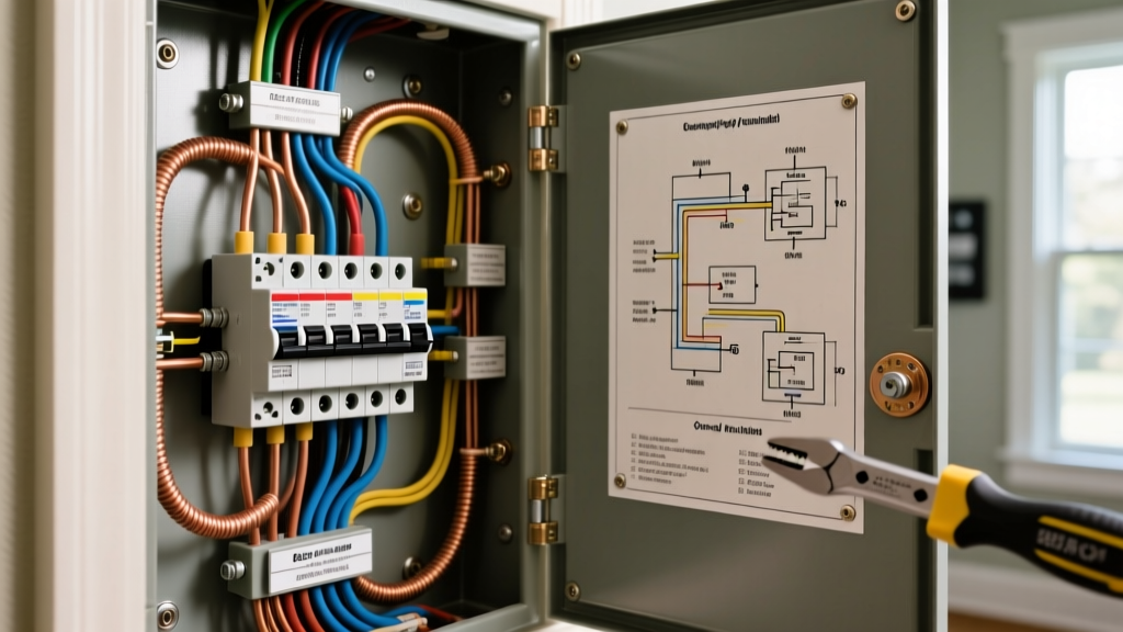
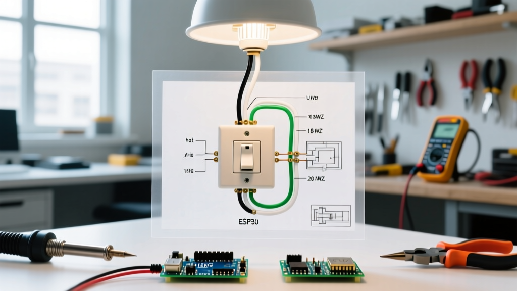
When designing a residential subpanel, commercial HVAC control board, or industrial motor starter, your schematic is the ultimate source of truth. However, a common point of failure in 2026 electrical design is the disconnect between the digital schematic and the physical wire being pulled. If your electrical wiring diagram maker does not support accurate American Wire Gauge (AWG) line-weight scaling and strict National Electrical Code (NEC) color mapping, you risk catastrophic installation errors. According to the NFPA National Electrical Code, proper conductor identification and sizing are not just best practices—they are strict legal requirements under articles like NEC 310.12 and 210.5. This guide breaks down how to leverage modern diagramming software to accurately represent wire gauges and color codes, ensuring your digital blueprints translate flawlessly to physical builds.
2026 Software Comparison: Which Diagram Maker Handles Gauges Best?
Not all diagramming tools are created equal when it comes to electrical engineering. While generic drawing apps allow you to change line colors, dedicated electrical software maps wire numbers to specific physical properties. Below is a comparison of the top tools used by electricians and engineers in 2026.
| Software | 2026 Pricing | AWG Line-Weight Scaling | Native NEC/IEC Palettes | Best Use Case |
|---|---|---|---|---|
| AutoCAD Electrical | ~$1,955 / yr | Advanced (Layer-based mapping) | Full IEC / IEEE / NFPA | Industrial Panels & PLCs |
| Wondershare EdrawMax | ~$99 / lifetime | Manual (Stroke width adjustment) | Basic NEC Hex Codes | DIY, Residential, Solar |
| SmartDraw | ~$119 / yr | Manual (Line weight tool) | Custom Hex Inputs | Commercial HVAC & Lighting |
| ProfiCAD | ~$49 (Home Ed.) | Wire Number Mapping | Custom Layer Colors | Quick Schematics & Netlists |
Configuring Line Weights to Represent AWG Sizes
In physical wiring, a 2 AWG feeder cable is significantly thicker than a 16 AWG control wire. If your schematic draws both with a standard 1-point line, installers may misjudge the required hardware. For example, using a #4 AWG crimping die on a 2 AWG lug because the diagram "looked thin" results in a high-resistance connection, leading to thermal runaway under continuous load.
Recommended Line Weight Mapping for EdrawMax & SmartDraw
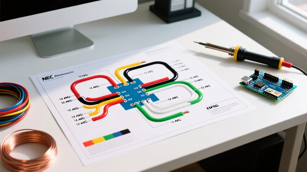
Since budget-friendly tools like EdrawMax don't auto-scale wires based on AWG databases like AutoCAD does, you must manually configure your stroke widths. Use this standard mapping to maintain visual hierarchy:
- Control Wires (18 - 14 AWG): Set line weight to 1.0 pt. Use dashed lines for low-voltage DC control circuits.
- Branch Circuits (12 - 8 AWG): Set line weight to 2.0 pt. Solid lines for standard 120V/240V AC.
- Feeders & Service Entrance (6 - 2/0 AWG): Set line weight to 4.0 pt. This visually warns the installer that heavy-duty lugs, larger conduit bends, and specific pulling compounds are required.
Expert Troubleshooting Tip: Always include a "Line Weight Legend" in the title block of your schematic. Installers working in the field often view schematics on tablets in direct sunlight; a legend ensures the thickness distinction isn't lost to screen glare.
Standard Reference: NEC vs. IEC Color Codes for Diagramming
Color coding in schematics must match the physical jacket colors of the wires being pulled. The OSHA electrical safety guidelines heavily rely on proper color identification to prevent shock hazards during maintenance. Furthermore, global projects require adherence to the IEC international standards. Below is a quick-reference matrix for configuring your software's color palette.
| AWG Size | mm² Equiv. | Ampacity (75°C Col.) | NEC 240.4(D) Limit | NEC Color (Hot) | IEC Color (Hot) |
|---|---|---|---|---|---|
| 14 AWG | 2.08 | 20A | 15A Max | Black (#000000) | Brown (#5C3317) |
| 12 AWG | 3.31 | 25A | 20A Max | Black / Red (#FF0000) | Brown / Black |
| 10 AWG | 5.26 | 35A | 30A Max | Red / Orange | Brown |
| 6 AWG | 13.30 | 65A | N/A (Standard 310.16) | Blue (#0000FF) | Grey (#808080) |
| 2 AWG | 33.62 | 115A | N/A | Orange / Brown | Grey |
Note: While the 75°C column in NEC Table 310.16 lists 14 AWG THHN at 20A, NEC 240.4(D) strictly limits the overcurrent protection device (breaker) to 15A for general branch circuits. Your diagram maker's bill of materials (BOM) must reflect the 15A breaker, not the 20A wire ampacity.
Step-by-Step: Setting Up Wire Layers in ProfiCAD
ProfiCAD is a favorite among panel builders because it uses wire numbers to generate netlists, but setting up the visual colors requires a specific workflow. Here is how to configure it for a standard 120V/240V split-phase residential panel:
- Open the Wire Properties Dialog: Press
F6or double-click an existing wire segment. - Assign Wire Numbers: Use the L1, L2, N, and PE prefixes. For example, L1-101 for Phase A, N-101 for Neutral.
- Map Colors to Prefixes: Go to Settings > Wire Colors. Assign Hex
#000000(Black) to all wires starting with "L1". Assign Hex#FF0000(Red) to "L2". Assign#FFFFFF(White) to "N" and#00FF00(Green) to "PE". - Enable Color Printing: ProfiCAD defaults to black-and-white for standard laser printing to save ink. Navigate to File > Print > Options and check "Print wires in color" if you are generating a digital PDF for a tablet-based field install.
Real-World Failure Modes: When Diagrams Mislead Installers
Beyond gauge and color, the routing implied by a diagram maker can cause physical failures. A common mistake in HVAC control schematics is drawing the 24V thermostat wires parallel and adjacent to the 240V compressor contactor feed. While the diagram maker might show them as distinct colors (e.g., solid blue for 24V, black/red for 240V), failing to add a physical separation note or a dashed "barrier" line on the schematic often results in the installer zip-tying the low-voltage and high-voltage wires together inside the conduit. This induces electromagnetic interference (EMI), causing smart thermostats to drop Wi-Fi connections or misread sensors. Always use your software's "annotation" tools to explicitly call out NEC 300.3(C) separation requirements on the blueprint.
Conclusion
Choosing the right electrical wiring diagram maker in 2026 goes far beyond simple drag-and-drop convenience. Whether you are paying $1,955 a year for AutoCAD Electrical's automated layer mapping or using a $99 lifetime license of EdrawMax with manual stroke-width adjustments, the goal remains the same: bridging the gap between digital design and physical reality. By strictly mapping line weights to AWG sizes and locking your color palettes to NEC 310.12 and IEC standards, you eliminate guesswork, prevent overheating failures, and ensure your installations pass inspection on the first try.