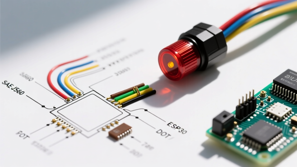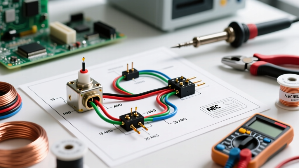

Decoding the Wiring Diagram for Float Switch Applications
Whether you are automating a residential sump pump, managing an industrial chemical tank, or wiring a 24V HVAC condensate safety pan, interpreting a wiring diagram for float switch integration requires more than just matching colors. The most common point of failure in fluid-level automation is not the switch itself, but improper wire gauge selection and misunderstood pigtail color codes. A mismatched American Wire Gauge (AWG) over a long run will cause severe voltage drop, leading to relay chatter, contact welding, and ultimately, catastrophic flooding or dry-run pump burnout.
In this comprehensive reference guide, we bridge the gap between theoretical schematics and real-world field wiring. We will dissect standard SPST (Single Pole Single Throw) and SPDT (Single Pole Double Throw) color codes, calculate exact wire gauge requirements based on the Cerrowire AWG ampacity standards, and outline step-by-step wiring protocols for both 120V AC line-voltage and 24V DC low-voltage control circuits.
Float Switch Pigtail Color Codes: SPST vs. SPDT
Before cutting any wire, you must identify the internal topology of your float switch. Manufacturers like Superior Pump, Rule, and LevelTec use specific color codes to denote the switch state. Misinterpreting these colors is the primary reason DIY installations fail to trigger at the correct liquid level.
1. Two-Wire SPST (Single Pole Single Throw)
Commonly found in basic sump pumps (e.g., Superior Pump 99005) and simple tank-fill applications. These act as a simple break/make in the circuit.
- Black Wire: Line / Hot (Incoming power)
- White Wire: Load (Outgoing to pump motor or relay coil)
- Green/Bare: Equipment Ground (if shielded cable is used)
Operational Note: Most 2-wire sump float switches are Normally Open (NO). The circuit closes (pump turns on) only when the float rises to the designated tether angle.
2. Three-Wire SPDT (Single Pole Double Throw)
Used in HVAC condensate pans, alarm systems, and dual-pump alternation panels. These provide both a Normally Open (NO) and a Normally Closed (NC) contact sharing a Common (C) terminal.
- Black Wire: Common (C) - Connect to the control voltage source.
- White Wire: Normally Open (NO) - Circuit closes when liquid rises (used for high-level alarms or pump activation).
- Red or Blue Wire: Normally Closed (NC) - Circuit opens when liquid rises (used for low-level cut-offs to prevent dry running).
Expert Field Tip: Never assume the white wire is a neutral in a 3-wire float switch pigtail. In control circuits, white is almost universally the NO load leg. Always verify continuity with a multimeter before applying power.
Wire Gauge Selection Matrix for Float Switches
Selecting the correct wire gauge is dictated by the National Electrical Code (NEC) and the physical distance between the float switch and the control panel or motor. According to NFPA 70 (NEC), voltage drop for branch circuits should not exceed 3%. When wiring a float switch in a deep well or a sprawling agricultural facility, the wire run can easily exceed 100 feet, necessitating a gauge upgrade.
| Application Type | Voltage / Current | Recommended AWG | Max Run (3% Drop) | Wire Type / Jacket |
|---|---|---|---|---|
| 24V HVAC Condensate (Class 2) | 24V AC/DC / <1A | 18 AWG | 75 feet | 18/2 Thermostat (CL2) |
| Standard Sump Pump (Direct Wire) | 120V AC / 10A - 15A | 14 AWG | 100 feet | SJTW (Water Resistant) |
| Heavy Duty Effluent Pump | 120V AC / 16A - 20A | 12 AWG | 120 feet | SJTW or THHN in Conduit |
| Long-Distance Agricultural Tank | 120V AC / 10A | 10 AWG | 200+ feet | UF-B (Direct Burial) |
Calculating Voltage Drop for Long Pigtail Runs
If you are extending the factory pigtail of a LevelTec LTS-OA switch to a control panel 150 feet away, using standard 18 AWG wire will result in a massive voltage drop, potentially starving the 24V relay coil of the pull-in voltage required to close the contact. Use the formula: Voltage Drop = (2 x L x R x I) / 1000 (where L is length in feet, R is resistance per 1000ft, and I is current in amps). When in doubt, bump up one AWG size for runs over 50 feet.
Step-by-Step Wiring Scenarios
Scenario A: Direct 120V AC Sump Pump Wiring (2-Wire)
This is the standard configuration for a piggyback plug or direct-wired 120V sump pump float switch.
- Disconnect Power: Turn off the 120V breaker at the main panel. Verify zero voltage with a non-contact tester.
- Prepare the Cable: Strip 3/4 inch of insulation from the 14 AWG SJTW cable. If the environment is damp, slide a piece of dual-wall marine heat shrink tubing over the cable before making connections.
- Make the Connections: Connect the incoming Hot (Black) to the Float Switch Black. Connect the Float Switch White to the Pump Motor Hot (Black).
- Neutral & Ground: Wire the incoming Neutral (White) directly to the Pump Motor Neutral (White). Bond the bare copper ground to the pump chassis ground screw.
- Seal and Secure: Slide the marine heat shrink over the wire nuts and apply heat until the adhesive sealant purges from the ends. This prevents sulfur and moisture from corroding the copper strands.
Scenario B: 24V DC Control Circuit for HVAC (3-Wire SPDT)
Used to trigger an alarm or shut off an AC compressor when a condensate pan fills up.
- Identify Terminals: Locate the 24V C (Common) and Y (Compressor Contactor) terminals on your HVAC control board.
- Wire the Common: Run an 18 AWG wire from the control board 24V C terminal to the Black wire of the float switch.
- Wire the Load (NO): Connect the White (NO) wire of the float switch to the alarm buzzer or the safety interrupt terminal on the control board.
- Test the Logic: Manually lift the float. The internal micro-switch should click, completing the 24V circuit and triggering the alarm or dropping out the contactor.
Edge Cases and Failure Modes in Float Switch Wiring
Even with a perfect wiring diagram for float switch setups, environmental and electrical edge cases can cause system failure. Recognizing these will save you hours of diagnostic time.
1. Inductive Kickback and Contact Welding
When a float switch directly switches an inductive load (like a 1/2 HP sump pump motor), the collapsing magnetic field when the switch opens generates a massive voltage spike. Over time, this arc pits the internal contacts, eventually welding them together in the 'ON' position. Solution: Never wire a float switch directly to a motor exceeding 10 Amps. Use the float switch to trigger the coil of a heavy-duty contactor or an interposing relay, allowing the contactor to handle the inductive load.
2. Capillary vs. Tethered Switch Wire Fatigue
Tethered float switches swing in a wide arc, putting mechanical stress on the pigtail exit gland. If standard solid-core THHN wire is used for pigtails, it will snap internally within months. Always ensure your extension wiring utilizes stranded copper with a flexible jacket like SJTW or SOOW to withstand continuous mechanical flexing.
3. False Triggering from EMI
In industrial settings, running low-voltage (24V) float switch wires parallel to high-voltage VFD (Variable Frequency Drive) cables can induce electromagnetic interference (EMI), causing the PLC to register false high-level alarms. Route control wiring in separate conduit or use shielded twisted-pair (STP) cable, grounding the shield at the panel side only.
Troubleshooting with a Multimeter
When a pump fails to activate, isolate the float switch from the circuit. According to Fluke's continuity testing guidelines, set your digital multimeter to the continuity setting (the diode/sound wave icon).
- Test NO (Black to White): With the float hanging down, the meter should read 'OL' (Open Loop). Lift the float; the meter should beep (near 0.0 ohms).
- Test NC (Black to Red): With the float hanging down, the meter should beep. Lift the float; the meter should read 'OL'.
If the switch shows continuity in both positions, or infinite resistance in both, the internal micro-switch has failed or the pigtail has suffered an internal break, requiring immediate replacement.
Final Code Compliance Reminders
Always adhere to local electrical codes when extending float switch wiring. For line-voltage (120V/240V) splices made inside a sump pit or wet well, standard wire nuts are a code violation. You must use waterproof, gel-filled wire connectors or encapsulate the splice in a NEMA 6P rated junction box. For low-voltage Class 2 circuits, ensure your 18 AWG wire carries a CL2 or CL3 rating if routed inside walls or air plenums to meet fire safety standards.