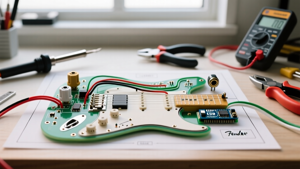

The Anatomy of Telecaster Electronics
The Fender Telecaster is arguably the most iconic solid-body electric guitar in history, largely due to its deceptively simple, robust, and highly musical electronic circuit. Unlike the complex switching matrices found in modern super-strats, the standard Telecaster relies on a minimalist approach: two single-coil pickups, a 3-way selector switch, one volume potentiometer, and one tone potentiometer. However, simplicity leaves no room for error. A poorly executed wiring diagram for Fender Telecaster circuits will immediately result in lost high-end frequencies, microphonic squeal, or debilitating 60-cycle hum.
In this comprehensive walkthrough, we will dissect the modern standard Telecaster wiring scheme. We will move beyond generic schematics and provide exact part numbers, soldering temperatures, and physical routing techniques used by professional luthiers in 2026.
Modern vs. Vintage: The Capacitor Debate
Before picking up your soldering iron, you must decide between the 'Modern' and 'Vintage' (pre-1967) wiring paradigms. The modern circuit utilizes a 0.047µF capacitor and provides a standard tone roll-off across all switch positions. The vintage circuit originally used a 0.1µF capacitor and featured a 'dark preset' circuit in the neck position, bypassing the tone knob entirely. For this guide, we are executing the Modern Standard wiring, which is the preferred configuration for 95% of contemporary players seeking maximum versatility.
Essential Tools and Component Matrix
Using substandard components is the leading cause of 'tone suck'—the imperceptible loss of high-frequency harmonics caused by out-of-spec potentiometers and cheap ceramic capacitors. Below is the exact bill of materials required for a professional-grade Telecaster harness.
| Component | Specification / Part Number | Why It Matters |
|---|---|---|
| Potentiometers (x2) | CTS 450G Series 250k Audio Taper (Part# 0022) | Audio taper provides a natural, logarithmic volume swell. 450G series guarantees a tight ±8% tolerance. |
| Capacitor | Sprague Orange Drop 715P, 0.047µF, 600V | Superior dielectric stability compared to cheap ceramic discs; preserves acoustic resonance. |
| Selector Switch | Oak Grigsby 4-Pole 3-Way Lever (Part# 150) | Heavy-duty brass contacts prevent the intermittent signal drop-outs common in cheap import switches. |
| Hookup Wire | 22 AWG Stranded Push-Back Cloth Wire | Cloth insulation eliminates the need for messy heat-shrink tubing and allows for easy stripping. |
| Solder | Kester 24-6040-00276 (60/40 Rosin Core, 0.031') | Leaded 60/40 solder flows at lower temperatures, protecting delicate switch wafers from heat damage. |
Required Tools: A temperature-controlled soldering station (like the Hakko FX-888D) set to 700°F (370°C), a damp cellulose sponge for tip cleaning, flush cutters, and a digital multimeter for continuity testing.
Step-by-Step Wiring Walkthrough
Phase 1: Component Preparation and Tinning
The most common mistake DIYers make is attempting to solder directly to cold lugs. You must 'tin' your components first. Apply a small amount of flux to the lugs of your CTS potentiometers and the Oak Grigsby switch. Touch your 700°F iron to the lug, feed a tiny bead of Kester solder until it flows into a smooth, shiny dome, and remove the heat. This process should take no more than 1.5 seconds per lug to prevent melting the internal phenolic wafers of the switch.
Pro Tip: Rough up the back casing of both potentiometers with 220-grit sandpaper and tin a large ground pad on each. This will serve as your primary grounding point for the circuit.
Phase 2: Wiring the Oak Grigsby 3-Way Switch
The Oak Grigsby 4-pole switch can be intimidating due to its eight lugs (four on side A, four on side B). We will only use specific lugs for the standard modern wiring:
- Bridge Pickup Hot: Solder the white (hot) wire from your bridge pickup to Lug A1.
- Neck Pickup Hot: Solder the white (hot) wire from your neck pickup to Lug A3.
- Volume Feed: Run a jumper wire from Lug A2 (the common output lug for side A) to Lug 1 on your Volume potentiometer.
- Tone Feed: Run a jumper wire from Lug B2 to one side of your Sprague Orange Drop capacitor.
- Switch Ground: Solder a ground wire from Lug B1 to the back casing of the Volume pot.
Phase 3: Potentiometer and Capacitor Integration
With the switch wired, we move to the control plate. The CTS volume and tone pots must be wired to interact seamlessly.
- Volume Pot: Lug 1 receives the hot feed from the switch (Lug A2). Lug 2 (the wiper) is your main output—run a wire from Lug 2 to the hot lug of your output jack. Lug 3 is bent back and soldered directly to the pot casing for a clean ground.
- Tone Pot: The free leg of your 0.047µF Orange Drop capacitor solders to Lug 1 of the Tone pot. Lug 2 is left completely unused (snip it flush to prevent accidental shorting). Lug 3 is soldered to the Tone pot casing.
Luthier's Insight: Never wrap the capacitor leg directly around the pot lug before soldering. The mechanical stress can crack the epoxy seal on the Orange Drop, leading to moisture ingress and capacitance drift over time. Simply lay the tinned wire against the tinned lug and apply heat.
Phase 4: Grounding and Shielding
A Telecaster is notorious for 60-cycle hum if the bridge plate is not properly grounded. You must run a bare or cloth-covered ground wire from the back of the Volume pot directly through the body routing channel to the bridge cavity. This wire gets pinched between the metal bridge plate and the wood body, grounding your strings and the bridge pickup's metal baseplate simultaneously.
Ensure that the neck pickup's metal cover (if equipped) also has its dedicated ground tab soldered to the back of the Volume pot. This creates a 'star ground' topology, minimizing the risk of ground loops that cause low-frequency hum.
Common Wiring Faults and Troubleshooting
Even with a perfect schematic, physical execution can introduce faults. Use your digital multimeter in continuity mode to diagnose these common edge cases:
1. The 'Scratchy' Potentiometer
If your volume pot crackles when turned, you likely overheated Lug 1 during the tinning phase, melting the internal resistive carbon track. Solution: There is no fix for a heat-damaged track; the CTS pot must be replaced. Always use a heat-sink clip on the lug when soldering near the casing.
2. Out-of-Phase 'Quack' in Middle Position
If position 2 (both pickups) sounds thin, hollow, and lacks bass, your pickups are out of phase. This happens if you are mixing a standard-wound bridge pickup with a reverse-wound/reverse-polarity (RWRP) neck pickup without adjusting the grounds. Solution: Swap the hot and ground wires on the neck pickup at the switch lugs, ensuring the pickup cover ground remains tied to the system ground to avoid shock hazards.
3. Microphonic Squeal at High Gain
If the bridge pickup squeals when facing your amplifier, the issue is rarely the wiring diagram itself, but rather a lack of wax potting or a loose ground on the bridge plate. Ensure the copper foil shielding in the bridge cavity is making direct contact with the bridge plate's ground wire.
Authoritative References and Further Reading
For visual schematics and alternative wiring modifications (such as the 4-way switch mod for series humbucking tones), consult these industry-standard resources:
- Seymour Duncan Pickup Wiring Diagrams Hub - The definitive database for color-code matching and alternate switching matrices.
- StewMac Tech Info & Wiring Resources - Excellent visual guides on physical component placement and control plate routing.
Mastering the wiring diagram for Fender Telecaster guitars is a rite of passage for any electronics DIYer. By adhering to strict component tolerances, utilizing proper heat management, and executing a flawless star-ground topology, you will unlock the true, unadulterated twang that has defined popular music for over seven decades.