
The Life-Safety Imperative in Access Control
When securing a commercial or multi-family residential building, the wiring diagram for magnetic door lock systems is not just about keeping unauthorized personnel out; it is fundamentally about ensuring safe, unimpeded egress during an emergency. As of the 2026 enforcement cycles for both NFPA 70 (National Electrical Code) and NFPA 101 (Life Safety Code), inspectors are cracking down on access-controlled egress doors that fail to drop power instantaneously during a fire alarm event.
Magnetic locks (maglocks) rely on electromagnetism to secure a door. Because they have no moving parts, they are incredibly reliable. However, this reliability becomes a fatal flaw if the electrical circuit is not designed to fail open. This guide provides a comprehensive, code-compliant wiring architecture, component specifications, and troubleshooting protocols to ensure your installation passes inspection and protects human life.
Fail-Safe vs. Fail-Secure: The Egress Mandate
Before routing a single wire, you must understand the legal and physical distinction between fail-safe and fail-secure hardware. According to NFPA 101 Life Safety Code, any door serving as a required means of egress must default to an unlocked state upon loss of power.
- Fail-Safe (Maglocks): Require continuous power to remain locked. If the fire alarm trips or the power grid fails, the electromagnet de-energizes, and the door swings open. Maglocks are inherently fail-safe and are legally permitted on egress routes when integrated with proper release mechanisms.
- Fail-Secure (Electric Strikes): Require power to unlock. If power fails, the door remains locked. These are strictly prohibited on primary egress routes unless paired with mechanical panic hardware.
Code Warning: Never wire a maglock to a circuit that is backed up by an Uninterruptible Power Supply (UPS) unless the UPS is specifically monitored and dropped by the Fire Alarm Control Panel (FACP) during an active fire event. OSHA 1910.37 mandates that exit routes must be free of obstructions and unlocked during occupancy.
Core Wiring Architecture: Step-by-Step Flow
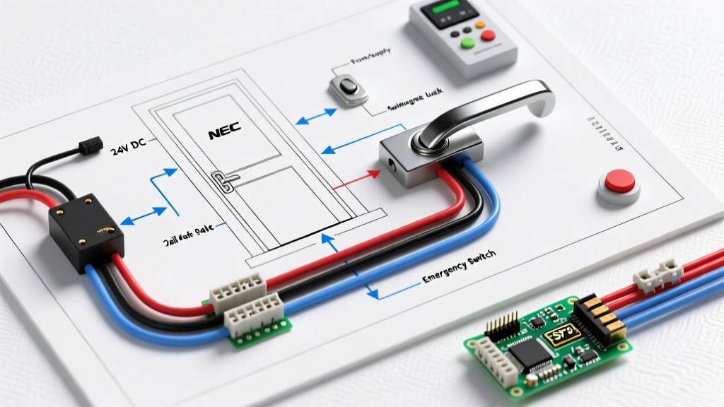
A compliant maglock installation requires a dedicated, regulated power supply, a Request to Exit (REX) sensor, a mechanical push-to-exit button, and FACP integration. Below is the logical wiring sequence.
1. AC Mains to Regulated Power Supply
Run a dedicated 120VAC circuit from your breaker panel to a regulated, UL-listed access control power supply (e.g., Altronix SMP3). Per NEC Article 725, the 120VAC wiring must be physically separated from the low-voltage DC wiring inside the enclosure to prevent inductive interference and shock hazards.
2. Fire Alarm Control Panel (FACP) Integration
This is the most critical life-safety step. The positive DC output from your power supply must first route through a Normally Closed (NC) relay on the FACP. When the fire alarm triggers, the FACP opens this relay, instantly cutting power to the entire maglock circuit, regardless of REX sensors or keypad states.
3. Request to Exit (REX) and Mechanical Override
From the FACP relay, the DC positive line splits to two egress triggers wired in parallel: 1. An overhead motion sensor (PIR REX). 2. A mechanical Push-to-Exit (PTX) button mounted at ADA-compliant heights (between 34 and 48 inches from the finished floor).
When either the REX or PTX is activated, it breaks the circuit, dropping power to the magnet and allowing the door to open.
4. The Electromagnet and Armature
The negative DC line runs directly from the power supply to the negative terminal on the maglock. The positive line completes the circuit from the REX/PTX switches to the positive terminal on the maglock.
Component Specifications & Real-World Pricing
To ensure reliability and pass UL inspections, avoid generic, unbranded hardware. Below are industry-standard components used in 2026 commercial installations:
| Component Type | Recommended Model | Key Specifications | Est. Cost (2026) |
|---|---|---|---|
| Magnetic Lock | Seco-Larm M-352-Q | 1200 lbs holding force, 12/24 VDC, auto-sensing | $165.00 |
| Power Supply | Altronix SMP3 | 12/24 VDC, 3A output, FACP interface, UL 294 listed | $95.00 |
| REX Sensor | Von Duprin 6300 Series | PIR motion, adjustable range, relay output | $125.00 |
| Push-to-Exit | SD-952-PTX | Stainless steel, single-gang, NC contact | $35.00 |
Wire Gauge Selection & Voltage Drop Matrix
Maglocks are highly sensitive to voltage drop. A 1200 lb maglock operating at 12VDC requires a minimum of 10.5VDC at the coil to maintain full holding force. If the voltage drops below this threshold, the lock may fail to secure the door against forced entry, or worse, the coil will overheat and burn out. Use the following matrix to select the correct copper wire gauge based on the distance from the power supply to the door frame.
| Distance (Power Supply to Lock) | 12 VDC System (1 Amp Draw) | 24 VDC System (0.5 Amp Draw) |
|---|---|---|
| Under 25 Feet | 18 AWG | 18 AWG |
| 25 to 50 Feet | 16 AWG | 18 AWG |
| 50 to 100 Feet | 14 AWG | 16 AWG |
| 100 to 200 Feet | 12 AWG | 14 AWG |
Note: Always calculate voltage drop using the total round-trip distance (positive and negative conductors). If running conduit outdoors, ensure you are using plenum-rated or wet-location rated cable (e.g., CMP or CMR) as dictated by NEC Article 725.
Addressing Residual Magnetism
A common edge case in maglock installations is residual magnetism. Over time, the steel armature plate can become slightly magnetized, causing the door to 'stick' for 3 to 5 seconds after power is cut. In a fire evacuation scenario, a 5-second delay can be catastrophic and is an immediate code violation.
The Solution: Modern maglocks like the Seco-Larm M-Series include an internal anti-residual magnetism circuit. Ensure the provided capacitor or jumper is correctly installed across the lock terminals as per the manufacturer's schematic. Additionally, verify that the rubber washer between the armature plate and the door is intact; this washer provides the necessary micro-gap to break the magnetic field instantly upon de-energization.
Top 3 Code Violations to Avoid During Inspection
- Missing Mechanical Egress: Relying solely on an overhead PIR motion sensor for egress. If the sensor fails or misreads a person standing still, they are trapped. A mechanical Push-to-Exit button wired in parallel is mandatory in almost all jurisdictions.
- Improper FACP Relay Wiring: Wiring the FACP drop to a Normally Open (NO) relay instead of Normally Closed (NC). This requires the fire panel to actively send a signal to unlock the door, which violates the fail-safe mandate if the fire panel's control board fries before sending the signal.
- Shared Power Supplies: Powering the maglock and the door's access control reader (e.g., HID iCLASS) on the same unregulated power tap without isolation. The voltage spike from the maglock de-energizing can reboot or destroy the reader's logic board. Always use a power supply with isolated, fused outputs.
Final Testing and Commissioning Protocol
Before signing off on the installation, perform the 'Drop Test'. Energize the system, engage the lock, and verify it holds 1200 lbs of force. Next, manually trip the FACP test switch. Use a digital multimeter at the maglock terminals to verify that voltage drops to 0.0VDC within 1.5 seconds of the alarm trigger. Finally, push the mechanical PTX button to ensure the circuit breaks cleanly. Document these multimeter readings and provide them to the local Authority Having Jurisdiction (AHJ) during your final walkthrough.