
The Shift to 12V DC: Why RV Ceiling Fans Need Specialized Wiring
When upgrading the climate control in a Class B camper van, Class C motorhome, or fifth-wheel toy hauler, installing a residential 120V AC ceiling fan is a common beginner mistake. Running a 120V fan requires firing up a 2000W+ inverter, which introduces a 10% to 15% power loss in conversion and rapidly drains your lithium battery bank. In 2026, the industry standard for off-grid and boondocking vehicles is the 12V DC Brushless DC (BLDC) fan. However, integrating these fans requires a precise wiring diagram for remote control ceiling fan systems adapted for high-vibration, 12V DC environments.
Unlike hardwired wall switches in residential homes, RV ceiling fans utilize Radio Frequency (RF) or Bluetooth receiver modules tucked into the canopy. This guide provides a comprehensive, vehicle-specific wiring diagram and installation protocol for 12V remote-controlled BLDC ceiling fans, ensuring compliance with RV electrical standards and eliminating common voltage-drop failures.
Component Breakdown: The 12V RV Fan Ecosystem
Before cutting into your RV’s roof cavity, you must understand the specific hardware involved. A premium 12V RV ceiling fan (such as the Kakadu 12V DC or adapted marine-grade Caframo models) typically retails between $180 and $280. The system comprises three main electrical nodes:
- The BLDC Motor: Draws between 1.2A and 3.5A depending on the speed setting. Unlike brushed motors, BLDC motors require a specific polarity and a steady DC voltage to prevent the internal ESC (Electronic Speed Controller) from faulting.
- The RF Receiver Module: A small PCB housed in the fan canopy. It steps down the logic voltage, processes the 433MHz remote signal, and routes power to the motor and integrated LED light kit.
- The Handheld Remote: Transmitting via RF, allowing control through the RV’s aluminum or fiberglass walls without requiring direct line-of-sight.
The Core 12V RV Wiring Diagram for Remote Control Ceiling Fan
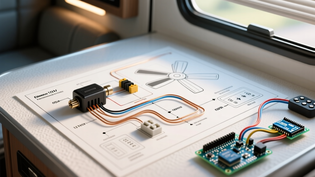
The following schematic outlines the exact wiring pathway from your RV’s 12V DC distribution busbar to the fan’s internal receiver. Because RVs are subject to constant road vibration and thermal expansion, this diagram prioritizes secure, vibration-resistant connections.
Step 1: Sizing the Wire and Overcurrent Protection
Voltage drop is the silent killer of 12V DC appliances. A typical BLDC fan with an LED light kit draws a maximum of 5 Amps. While 16 AWG wire can technically handle 5A, the distance from the RV’s main DC busbar to the ceiling often exceeds 20 feet. According to the Blue Sea Systems circuit sizing guidelines, you must account for a 3% voltage drop limit for critical electronics.
- Run under 15 feet: Use 14 AWG stranded marine-grade tinned copper wire.
- Run over 15 feet: Upgrade to 12 AWG stranded tinned copper wire to prevent the receiver module from browning out when the fan is set to high speed.
- Overcurrent Protection: Install a 10A inline automotive blade fuse (ATO/ATC) or a 10A breaker on the positive lead, positioned within 7 inches of the positive busbar connection.
Step 2: Routing Through the RV Roof Cavity
RV roofs are constructed with thin luan panels, EPS foam insulation, and a rubber EPDM or TPO membrane. When routing your 12 AWG wires from a sidewall conduit or an overhead cabinet to the fan canopy, never use solid THHN wire. The NFPA 1192 Standard on Recreational Vehicles strictly mandates the use of stranded copper wire to withstand vehicular vibration and flexing. Use a flexible fish tape to pull the red (positive) and black (negative) wires through the roof truss channels, ensuring they are secured with adhesive-backed cable clamps every 18 inches to prevent rattling.
Step 3: Terminating the RF Receiver Module
The receiver module inside the fan canopy typically features a 6-pin terminal block. Here is the exact termination sequence:
- VCC / 12V+ (Red Wire): Connect to the fused 12V positive lead from the busbar.
- GND / 12V- (Black Wire): Connect to the 12V negative lead routed back to the negative busbar. Do not ground to the RV chassis; RV chassis grounds are notoriously unreliable for sensitive RF logic boards and can introduce ground loops.
- M+ and M- (Motor Leads): Connect directly to the BLDC motor. Reversing these will not damage a BLDC motor, but it will cause the fan to spin in reverse (updraft instead of downdraft).
- L+ and L- (Light Leads): Connect to the integrated 12V LED light array.
Pro-Tip for High-Vibration Environments: Never solder wire connections in an RV ceiling. Solder creates a rigid joint that work-hardens and snaps under highway vibration. Instead, use adhesive-lined heat shrink butt crimps (rated for 12-10 AWG) and a proper ratcheting crimping tool to ensure a gas-tight, vibration-proof seal.
Remote Signal Interference & RV-Specific Failure Modes
Even with a perfect wiring diagram for remote control ceiling fan setups, RV environments introduce unique electromagnetic and structural challenges that residential electricians rarely face.
The Inverter EMI Problem
When your RV’s 3000W hybrid inverter/charger is actively converting 12V DC to 120V AC (e.g., running the microwave or roof air conditioner), it generates significant Electromagnetic Interference (EMI). This EMI can blanket the 433MHz spectrum, effectively blinding your fan’s RF receiver. If your fan remote only works when the inverter is turned off, you must relocate the receiver module closer to the bottom of the fan canopy, or wrap the receiver PCB in copper foil tape connected to a dedicated ground wire to shield it from inverter noise.
Aluminum Chassis Signal Blocking
In Airstreams or Avion trailers with riveted aluminum skins, the metal shell acts as a Faraday cage. If the fan is mounted near the rear of a 35-foot trailer and you are standing outside near the awning, the RF signal may fail to penetrate. Upgrading to a fan system that utilizes Bluetooth Low Energy (BLE) paired with a smartphone app often provides better signal penetration through composite and metal RV walls than traditional 433MHz RF remotes.
RV Ceiling Fan Troubleshooting Matrix
Use the following diagnostic matrix to troubleshoot common failures specific to 12V DC remote-controlled fans in motorhomes and travel trailers.
| Symptom | Root Cause | Diagnostic Step | Corrective Action |
|---|---|---|---|
| Fan stutters or stops on 'High' speed | Voltage drop at the receiver module | Multimeter test at receiver VCC/GND pins while fan is running | Upgrade wiring from 14 AWG to 12 AWG; check for corroded busbar connections |
| Remote pairs, but commands are ignored | 433MHz EMI from RV Inverter/Charger | Turn off the main inverter and test remote response | Apply copper shielding tape to receiver housing; reroute wiring away from inverter cables |
| Light works, but motor does not spin | BLDC internal ESC fault or reversed polarity | Verify M+ and M- continuity; listen for ESC click | Reset power at the busbar breaker for 60 seconds to reset the ESC logic board |
| Receiver forgets pairing after driving | Micro-voltage drops from loose crimps | Tug-test all wire crimps at the receiver terminal block | Re-crimp using adhesive-lined heat shrink; ensure ratcheting tool was fully engaged |
Final Inspection and Safety Compliance
Before securing the fan canopy to the RV ceiling mount, perform a load test. Turn the fan to its maximum speed and activate the LED light kit simultaneously. Use an infrared thermometer to check the temperature of the 10A inline fuse and the receiver module terminals. In a properly executed 12V RV circuit, the terminals should not exceed ambient temperature by more than 10°F (5°C). Secure the canopy using the provided vibration-dampening rubber grommets to prevent the mounting screws from transferring road noise into the hollow RV ceiling cavity.
By adhering to this vehicle-specific wiring diagram and utilizing marine-grade materials, your 12V remote control ceiling fan will provide reliable, ultra-low-draw air circulation for years of off-grid camping, completely eliminating the need to waste battery capacity on an inverter.