
Introduction to Multi-Location Switching Safety
Multi-location lighting control is a fundamental requirement in modern residential and commercial electrical design. However, the complexity of routing traveler wires between multiple junction points frequently leads to dangerous code violations. When reviewing a standard wiring diagram for 3 way and 4 way switches, electricians and advanced DIYers must look beyond basic functionality and prioritize National Electrical Code (NEC) compliance, thermal management, and long-term safety. In 2026, with the widespread adoption of smart lighting modules and stricter enforcement of box-fill regulations, understanding the precise mechanical and electrical requirements of these circuits is non-negotiable.
NEC Mandates Governing Multi-Location Switches
Before pulling any wire, you must understand the specific NEC articles that govern switch installations. The NFPA 70 (National Electrical Code) outlines strict parameters to prevent arc faults, overheating, and shock hazards.
- NEC 404.2(A) - Switching the Ungrounded Conductor: Switches must only break the hot (ungrounded) leg of the circuit. The grounded (neutral) conductor must never be routed through a standard mechanical switch as a switched leg, as this leaves the light fixture energized even when turned off, posing a lethal shock hazard during bulb changes.
- NEC 404.2(C) - Neutral Conductor Availability: Modern codes require a grounded (neutral) conductor to be present at nearly all switch locations. This is to accommodate smart switches, timers, and occupancy sensors that require a neutral path for their internal electronics. In a 4-way setup, the neutral must be pulled through every intermediate box, even if it is not terminated on the mechanical 4-way switch itself.
- NEC 250.148 - Equipment Grounding: All equipment grounding conductors (EGC) spliced within a switch box must be connected together, and a pigtail must be run to the metal yoke of the switch (if using standard metal boxes or metal-faced switches). Relying solely on the switch mounting screws for grounding is a severe violation.
Understanding the Topology: Line, Travelers, and Load
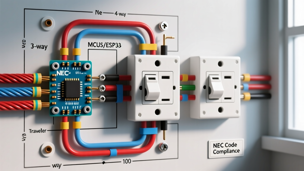
A compliant wiring diagram for 3 way and 4 way switches follows a strict linear topology. Power originates at the line source, enters the first 3-way switch, passes through any number of intermediate 4-way switches via traveler pairs, and terminates at the final 3-way switch before feeding the load (the light fixture).
The Role of the 4-Way Switch
A 4-way switch (such as the Leviton Decora 5604-2W) is essentially a double-pole, double-throw (DPDT) polarity-reversing switch. It does not have a 'common' or 'line/load' terminal. Instead, it features two pairs of terminals (often labeled IN and OUT, or differentiated by brass and black screws). Its sole function is to cross or pass straight the two traveler wires connecting the two 3-way switches. Reversing the IN and OUT pairs on a single 4-way switch will not break the circuit logic, but maintaining consistent orientation is critical for troubleshooting.
Traveler Wire Re-Identification (NEC 200.7)
When using standard NM-B (Romex) cable, you are often forced to use the white wire as a traveler or a switched hot. NEC 200.7(C)(2) strictly mandates that any white wire used as an ungrounded (hot) conductor must be permanently re-identified. You must wrap the ends of the white wire with colored electrical tape (e.g., 3M Super 33+ vinyl tape in red or blue) at every termination point. Failing to re-identify a white traveler wire is one of the most common reasons for failing a rough-in electrical inspection.
Box Fill Calculations: The Most Common Code Violation
Intermediate 4-way switch boxes are notorious for overcrowding. NEC Article 314.16(B) dictates strict volume allowances to prevent wire insulation damage and excessive heat buildup. Every conductor, clamp, and device yoke consumes a specific volume of cubic inches based on the wire gauge.
WARNING: Never force wires into an undersized junction box. Overcrowding degrades wire insulation over time, leading to short circuits and arc faults that standard breakers may not detect immediately.
| Wire Gauge (AWG) | Volume per Conductor | Device Yoke Allowance | Grounding Wire Allowance |
|---|---|---|---|
| 14 AWG | 2.0 cubic inches | 4.0 cubic inches (counts as 2) | 2.0 cubic inches (counts as 1) |
| 12 AWG | 2.25 cubic inches | 4.5 cubic inches (counts as 2) | 2.25 cubic inches (counts as 1) |
| 10 AWG | 2.5 cubic inches | 5.0 cubic inches (counts as 2) | 2.5 cubic inches (counts as 1) |
Practical Box Fill Example: The 4-Way Intermediate Box
Imagine a 4-way switch box where a 12/3 cable enters (Line/Neutral + 2 Travelers) and a 12/3 cable exits (2 Travelers + Neutral). Let us calculate the required box volume:
- Current-Carrying Conductors: 4 traveler wires (12 AWG) = 4 x 2.25 = 9.0 cu in.
- Neutral Wires: 2 neutral wires spliced together (12 AWG) = 2 x 2.25 = 4.5 cu in.
- Equipment Ground: 2 ground wires spliced (counts as 1) = 1 x 2.25 = 2.25 cu in.
- Device Yoke: The 4-way switch itself (counts as 2) = 2 x 2.25 = 4.5 cu in.
- Total Minimum Box Volume Required: 20.25 cubic inches.
A standard single-gang 'old work' drywall box is typically 14 to 18 cubic inches. Therefore, you must use a deep single-gang box (minimum 22 cu in) or a double-gang box with a mud ring to remain code-compliant for this specific 12 AWG 4-way setup.
Step-by-Step Code-Compliant Installation Guide
Follow these precise steps to ensure a safe, reliable, and inspector-approved installation. For this guide, we assume the use of modern lever-nut connectors (like the WAGO 221-413) which are vastly superior to traditional twist-on wire nuts for multi-wire splices in crowded boxes.
- Power Verification: Turn off the breaker and verify zero voltage using a non-contact voltage tester (NCVT) and a digital multimeter (DMM) testing between the hot and a known ground.
- Wire Stripping Precision: Strip exactly 11mm (7/16 inch) of insulation from solid copper conductors when using WAGO 221 lever nuts. Over-stripping exposes bare copper outside the connector, creating a shock hazard; under-stripping results in a high-resistance connection that will melt under load.
- Neutral Splicing: Bundle all white neutral wires together using a WAGO 3-port or 5-port connector. Do not attach these to the mechanical 4-way switch. Push the bundle deep into the back of the box to reserve space for the travelers and switch yoke.
- Grounding Pigtails: Connect all bare copper ground wires together and add a 6-inch green or bare pigtail. Terminate the pigtail to the green grounding screw on the switch yoke. Torque the ground screw to the manufacturer specification (typically 14 in-lbs for Leviton Decora devices) to prevent thermal creep.
- Traveler Termination: Connect the incoming pair of travelers to the 'IN' terminals of the 4-way switch, and the outgoing pair to the 'OUT' terminals. If using 12 AWG wire, utilize the side-wire terminal loops rather than the back-stab (push-in) holes, as back-stab connections are prone to failure and arcing over time.
- Box Dressing: Carefully fold the wires in an accordion pattern. Ensure no bare ground wires are resting against the brass traveler terminals, which could cause a dead short when the switch is screwed into the box.
Troubleshooting Edge Cases and Failure Modes
Even with a perfect wiring diagram for 3 way and 4 way switches, environmental factors and component degradation can cause issues. Here is how to diagnose complex failure modes safely.
Phantom Voltages on Disconnected Travelers
When troubleshooting with a high-impedance digital multimeter, you may read 40V to 90V on a disconnected traveler wire. This is 'phantom voltage' caused by capacitive coupling from adjacent energized wires running in the same NM-B cable. To verify if the voltage is real or phantom, switch your multimeter to a low-impedance (LoZ) setting or use a solenoid voltage tester (Wiggy). If the voltage disappears under load, it is harmless capacitive coupling.
Smart Switch Compatibility in 4-Way Circuits
Upgrading a mechanical 4-way circuit to smart control (e.g., Lutron Caseta) requires a fundamental rewiring. Smart systems generally do not use physical traveler wires for intermediate locations. Instead, the smart switch is installed at the load-end or line-end 3-way location, and the intermediate 4-way boxes are converted into simple pass-through junction boxes where the travelers are permanently wire-nutted together. Wireless Pico remotes are then mounted over the intermediate boxes. Always consult the specific manufacturer wiring guides before attempting smart switch retrofits, as improper neutral sharing can trip AFCI/GFCI breakers.
Frequently Asked Questions (FAQ)
Can I use a 4-way switch as a 3-way switch?
No. A 4-way switch lacks a 'common' terminal required to break the line or load connection. Attempting to jumper terminals to simulate a 3-way switch violates NEC 110.3(B) regarding equipment listing and installation instructions.
Does the direction of the 4-way switch matter?
Electrically, mounting a 4-way switch upside down or sideways does not affect its operation or violate code, provided the switch is accessible and the box fill is adequate. However, for aesthetic consistency and ergonomic operation, all switches in a multi-gang box should be oriented identically.
What happens if I switch the neutral instead of the hot wire?
The light will still turn on and off, but the light fixture socket will remain continuously energized with 120V. If a homeowner attempts to change a bulb or perform maintenance, they will complete the circuit to ground, resulting in a severe or fatal electrical shock. This is why verifying the ungrounded conductor with a voltage tester before termination is a critical safety step.
For further reading on workplace and residential electrical safety standards, refer to the OSHA Electrical Safety guidelines, which provide vital context on arc flash prevention and proper lockout/tagout (LOTO) procedures when working on multi-location switch circuits.