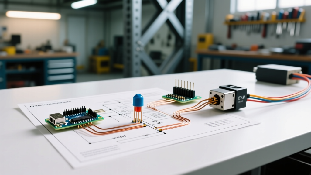

The Core Challenge: Motor Inrush vs. Photocell Limits
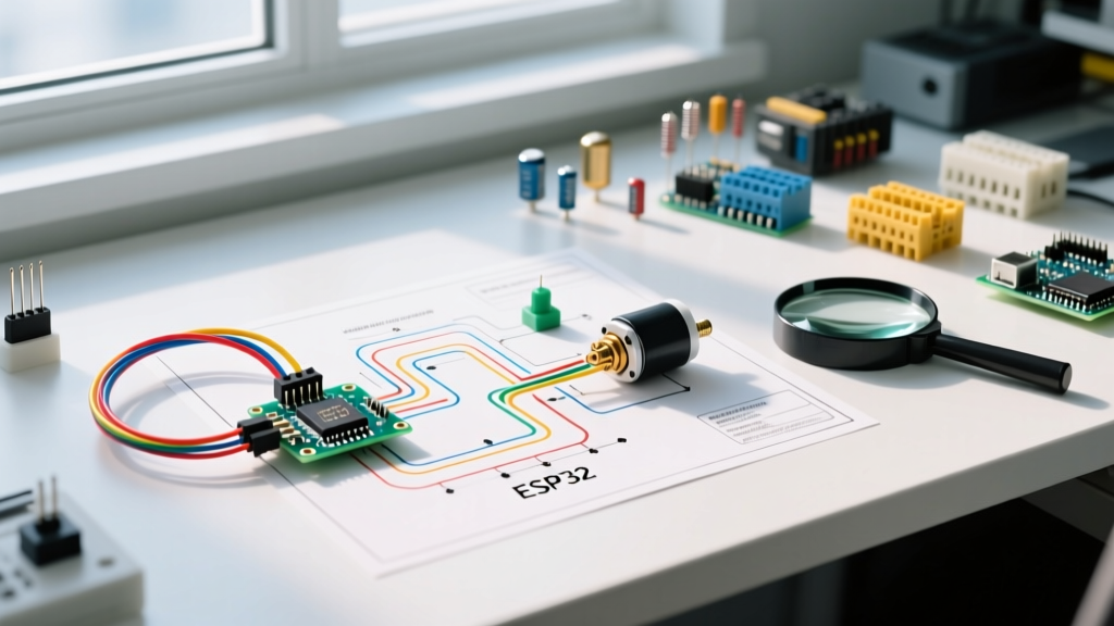
When technicians and DIYers search for a wiring diagram for a photocell, they are typically trying to solve one of two problems: automating an outdoor motor (like a pond pump, exhaust fan, or agricultural ventilator) using a dusk-to-dawn sensor, or integrating an industrial photoelectric sensor (photo-eye) into a conveyor or gate motor starter circuit. While the underlying physics of light detection is similar, the electrical architecture required to safely switch a motor load is vastly different from switching a simple LED or incandescent bulb.
The most critical concept to understand before wiring any photocell to a motor is Locked Rotor Amps (LRA). A standard 120V, 1/2 HP single-phase motor draws roughly 9.8 amps during normal operation. However, during startup (the first 100-200 milliseconds), the inrush current can spike to 60 amps or more. Standard dusk-to-dawn photocells utilize internal solid-state triacs or small mechanical relays rated for a maximum of 15A to 20A resistive loads. If you wire a motor directly to the load side of a standard photocell, the LRA spike will instantly weld the triac shut, causing the motor to run continuously and eventually burning out the sensor's internal circuitry.
2026 Industry Note: As of 2026, the widespread adoption of Brushless DC (BLDC) motors in HVAC and agricultural applications has altered traditional inrush profiles. While BLDC motors feature soft-start controllers that reduce LRA, the National Fire Protection Association (NFPA 70) still mandates that motor control circuits be isolated via properly rated contactors or motor starters to ensure compliance and prevent fire hazards.
Scenario A: Dusk-to-Dawn Photocell for Outdoor Motor Loads
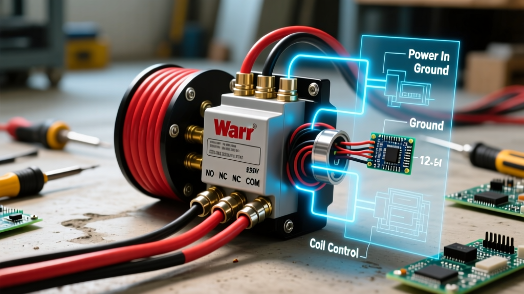
For outdoor applications such as automated greenhouse ventilation fans or wastewater lift station pumps, a standard cadmium-sulfide or photodiode-based dusk-to-dawn sensor is used. Because the photocell cannot handle the motor's inrush current, the wiring diagram must incorporate a Definite Purpose Contactor or an Ice-Cube Relay.
Required Components & 2026 Pricing
- Photocell: Intermatic K4021C (120V, 15A Tungsten rating) — Approx. $18.00
- Contactor: Packard C401A (120V Coil, 40A FLA Resistive, 30A FLA Inductive) — Approx. $26.00
- Wire: 14 AWG THHN (Line/Load/Neutral) and 18 AWG MTW (Control circuit) — Approx. $0.45/ft
Step-by-Step Wiring Logic
- Power Feed: Run your 120V AC Line (Black) and Neutral (White) from the main breaker panel to the control enclosure.
- Photocell Line: Connect the 120V Line to the Black wire of the Intermatic K4021C photocell.
- Control Circuit (Switched Leg): Connect the Red wire of the photocell to the A1 terminal on the contactor coil. This acts as your switched hot.
- Neutral Completion: Connect the 120V Neutral to both the White wire of the photocell and the A2 terminal on the contactor coil.
- Motor Power Circuit: Connect the main 120V Line to the L1 terminal on the contactor. Connect the T1 terminal to the hot lead of your motor.
- Motor Neutral & Ground: Wire the motor's neutral directly to the main Neutral bus. Bond the motor chassis and enclosure to the equipment grounding conductor (EGC) using 14 AWG bare copper or green THHN, per OSHA Electrical Standards.
When ambient light drops below 1.5 foot-candles, the photocell closes its internal circuit, sending 120V to the A1 coil. The contactor's magnetic field pulls the heavy-duty silver-alloy contacts closed, delivering full amperage to the motor without stressing the delicate photocell triac.
Scenario B: Industrial Photoelectric Sensor (Photo-Eye) Automation
In industrial motor control (e.g., conveyor belts, automated gates, or packaging lines), the term 'photocell' usually refers to a photoelectric sensor. These operate on low-voltage DC (typically 10-30VDC) and output a logic signal to a PLC or a motor starter relay, rather than switching AC line voltage directly.
Wiring a 3-Wire PNP Sensor to a Motor Starter
Let us use the industry-standard Omron E3Z-D62 (Diffuse reflective, PNP output, N.O., approx. $72.00) as our reference model. A PNP sensor switches the positive voltage to the load when the light beam is broken or reflected.
- Brown Wire: +24VDC Power Supply
- Blue Wire: 0VDC (Ground/Return)
- Black Wire: Control Output (Signal to Motor Starter Relay Coil)
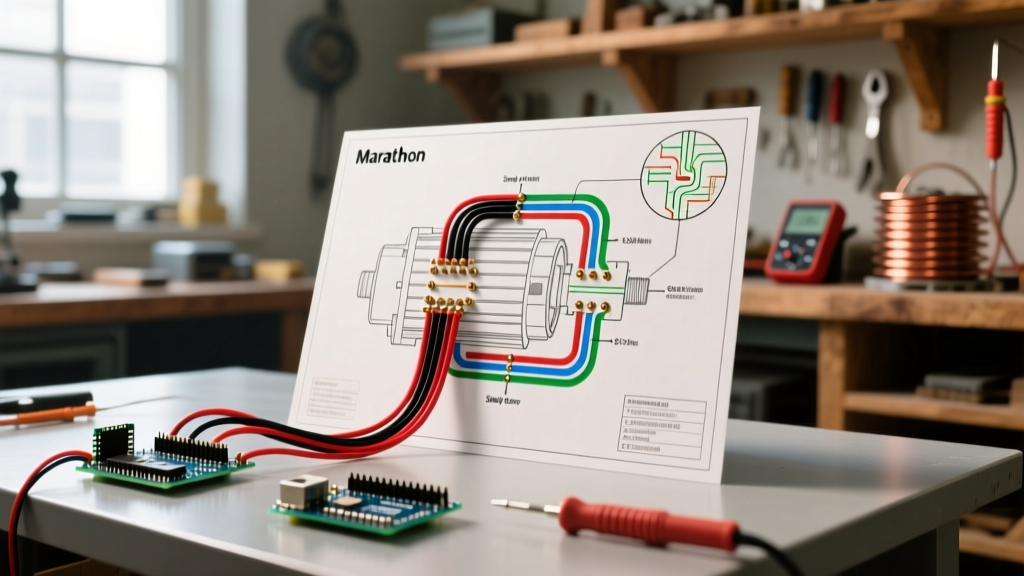
The Black wire is wired to the positive input of a 24VDC interface relay (such as a Phoenix Contact PLC-RSP- 24DC/21). The relay's dry contacts are then wired into the 120V or 24V control circuit of a NEMA-rated Motor Control Center (MCC) or a standard IEC motor starter. This ensures complete galvanic isolation between the sensitive 24VDC sensor logic and the noisy, high-inductance AC motor power circuit.
Photocell Types for Motor Control Comparison
| Feature | Dusk-to-Dawn (Photoresistor/Photodiode) | Industrial Photo-Eye (Photoelectric) |
|---|---|---|
| Primary Use | Outdoor lighting, exhaust fans, pumps | Conveyors, automated gates, robotics |
| Operating Voltage | 120V - 277V AC | 10V - 30V DC |
| Output Type | Internal Triac / Relay (AC Switching) | PNP / NPN Transistor (Logic Signal) |
| Direct Motor Wiring? | NO (Requires Contactor) | NO (Requires Interface Relay / PLC) |
| Avg. Response Time | 10 - 30 Seconds (Time Delay) | 1 - 5 Milliseconds |
Critical Failure Modes and Edge Cases
Even with a correct wiring diagram for a photocell, real-world environments introduce variables that cause system failures. Understanding these edge cases separates novice installers from master electricians.
1. Triac Welding from Capacitor Start Motors
Capacitor-start induction motors (common in air compressors and heavy-duty pumps) generate massive phase-shifted voltage spikes during startup. If a snubber circuit is not present across the contactor coil, the inductive kickback can arc across the photocell's internal components. Solution: Always install an RC snubber (e.g., a 0.1µF capacitor with a 100-ohm resistor) across the contactor coil terminals (A1 and A2) to absorb inductive spikes.
2. Sunlight Blinding in Industrial Photo-Eyes
When wiring outdoor gate motors using diffuse-reflective photo-eyes, direct afternoon sunlight can overwhelm the sensor's infrared receiver, causing the motor to stop unexpectedly or fail to start. Solution: Use polarized retro-reflective sensors with optical filters specifically tuned to the sensor's LED wavelength (usually 660nm red or 880nm IR), and mount the sensor at a 5-degree downward angle to avoid direct solar incidence.
3. Voltage Drop on Long Sensor Runs
Running 18 AWG sensor wire over distances greater than 50 feet in agricultural settings often results in a voltage drop below the 10VDC minimum threshold required by the photo-eye, leading to intermittent motor stuttering. Solution: For runs exceeding 50 feet, step up to 16 AWG or 14 AWG stranded wire for the 24VDC power supply lines, keeping the signal wire at 18 AWG but utilizing shielded cable (Belden 8761) tied to ground at the panel only to prevent ground loops.
Final Safety Verification
Before energizing any motor circuit controlled by a photocell, perform a continuity test with a multimeter. Verify that the photocell's load side is completely isolated from the motor's main power feed, confirming that the photocell only carries the low-amperage load of the contactor coil (typically 0.05A to 0.2A). Proper adherence to these isolation principles ensures a system lifespan measured in decades, rather than days.