
The Anatomy of a 120V Interconnected Smoke Detector Circuit
When designing or retrofitting a residential fire safety system, understanding the correct wiring diagram for smoke detectors is a matter of life and death. Hardwired, interconnected smoke alarms are the gold standard for residential fire safety, mandated by the National Electrical Code (NEC) and NFPA 72 for all new construction and major renovations. Unlike standalone battery-operated units, a hardwired system ensures that if a fire starts in the basement, the alarms in the third-floor bedrooms will sound simultaneously.
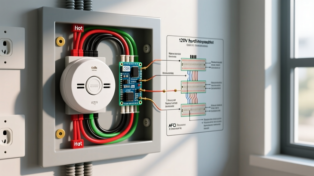
From an electrical perspective, a standard 120V hardwired smoke detector circuit requires a 3-wire NM-B (Romex) cable setup: a line (hot), a neutral, and an interconnect (traveler) wire. This guide breaks down the exact wiring topology, NEC Article 760 compliance requirements, and the specific installation parameters required to pass municipal inspections in 2026.
CRITICAL SAFETY WARNING: Always de-energize the circuit at the main service panel before beginning any wiring work. Verify the absence of voltage using a CAT III or CAT IV rated non-contact voltage tester, such as the Klein Tools NCVT-2. Never assume a wire is dead based solely on wall switch positions.
Standard 3-Wire Wiring Diagram Breakdown
The standard wiring topology for interconnected 120V smoke alarms (such as the widely used Kidde i12060 or First Alert SA720CN) utilizes 14 AWG or 12 AWG NM-B cable. The choice of gauge depends entirely on the overcurrent protection device (breaker) sizing the circuit.
Wire Color Coding and Terminal Functions
- Black Wire (Line/Hot): Connects to the 120V AC power source from the breaker panel. This provides continuous power to the alarm's internal circuitry and charges the backup battery.
- White Wire (Neutral): Completes the 120V AC circuit back to the panel's neutral bar. Code Violation Alert: Never use the ground wire as a neutral substitute; this will trip AFCI/GFCI breakers and create a severe shock hazard.
- Red Wire (Interconnect/Traveler): This is the communication wire that daisy-chains all alarms together. Modern alarms use a DC signaling protocol (typically 9V DC) over this red wire. When Alarm A detects smoke, it sends a DC voltage signal down the red wire to trigger the sounders in Alarms B, C, and D.
NEC Code Compliance & AFCI/GFCI Matrix
One of the most common reasons for failed electrical inspections regarding smoke detectors involves improper application of Arc-Fault (AFCI) and Ground-Fault (GFCI) protection. The NEC strictly regulates how life-safety circuits are protected to prevent nuisance tripping from disabling the fire alarm system.
| Protection Type | NEC Requirement for Smoke Alarms | Technical Rationale & Edge Cases |
|---|---|---|
| GFCI | STRICTLY PROHIBITED | Smoke detectors must never be installed on a GFCI-protected circuit. A nuisance ground-fault trip (e.g., from a shared bathroom exhaust fan) would silently disable the smoke alarm network. |
| AFCI (Bedrooms) | REQUIRED (with exceptions) | NEC 210.12 requires AFCI protection for bedroom outlets. If the smoke alarm is on the same circuit as bedroom receptacles, it must be AFCI protected. However, many local jurisdictions allow a dedicated non-AFCI circuit exclusively for smoke alarms to prevent arc-fault nuisance trips. |
| Dedicated Circuit | Highly Recommended | While the NEC allows smoke alarms to share a general lighting circuit, best practice (and some local codes) mandates a dedicated 15A breaker to ensure the alarms are not accidentally de-energized by a tripped shared breaker. |
NFPA 72 Placement and Spacing Rules
A perfect wiring diagram is useless if the physical placement of the detectors violates NFPA 72 National Fire Alarm and Signaling Code standards. Smoke rises and spreads laterally along the ceiling; improper placement creates 'dead air' pockets where smoke cannot reach the sensor.
- Ceiling Mount (Flat): Place the detector at least 4 inches away from any intersecting wall.
- Ceiling Mount (Pitched): Install the detector within 3 feet of the peak, but not at the absolute apex. Maintain a minimum 4-inch drop from the highest point to avoid the dead-air pocket at the peak.
- Wall Mount: If ceiling mounting is impossible, the top of the alarm must be between 4 inches and 12 inches below the ceiling line.
- HVAC Proximity: Detectors must be installed at least 3 feet away from the opening of any HVAC supply register to prevent rapid air movement from blowing smoke away from the sensor chamber.
Step-by-Step Hardwiring Procedure
Follow this precise sequence to ensure secure, code-compliant terminations. This procedure assumes a 15A dedicated circuit using 14/3 NM-B cable with ground.
- Prepare the Junction Box: Ensure you are using a UL-listed octagonal or round ceiling pan box. Calculate box fill according to NEC Article 314.16. A standard 4-inch round box (21 cubic inches) is generally sufficient for the 14/3 incoming and outgoing cables plus the alarm pigtail.
- Strip and Prep Conductors: Strip exactly 3/4 inch of insulation from the 14 AWG solid copper wires using a precision wire stripper (e.g., Klein 11055). Do not nick the copper, as this creates a weak point that can snap during folding.
- Terminate the Interconnect (Red) Daisy Chain: Using a WAGO 221-413 lever-nut or an Ideal 341 Orange wire nut, connect the incoming red wire, the outgoing red wire (to the next alarm), and the red pigtail from the smoke detector harness. The WAGO lever-nuts are highly recommended by professionals for their verifiable, secure connections on multi-wire interconnects.
- Terminate Line and Neutral: Connect the black wires (line, load, and pigtail) together, and the white wires (neutral, load, and pigtail) together. Pro-Tip: Use a separate wire nut for the black and white sets; never mix line and neutral under a single connector.
- Grounding: Connect the bare copper ground wires together with a green wire nut. If using a metal junction box, you must also attach a grounding pigtail to the box's green grounding screw.
- Mount and Test: Secure the mounting bracket to the box using the provided #8-32 machine screws. Attach the alarm base, plug in the 3-pin harness, and twist the alarm into the locked position. Install a fresh 9V alkaline or 10-year lithium backup battery, then press the 'Test' button to verify the interconnect signal triggers all downstream units.
Device Limits and Voltage Drop Calculations
You cannot daisy-chain an infinite number of smoke alarms. The interconnect wire carries a low-voltage DC signal, and excessive cable runs will cause voltage drop, resulting in downstream alarms failing to trigger.
According to the U.S. Fire Administration and manufacturer specifications:
- Kidde 120V Models (e.g., i12060): Maximum of 24 interconnected devices (of which no more than 18 can be smoke alarms; the rest can be heat or CO detectors).
- First Alert / BRK Models (e.g., SA720CN): Maximum of 18 interconnected devices.
- Mixed Brand Compatibility: Kidde and First Alert use different DC signaling protocols on the red interconnect wire. Mixing brands will result in the alarms sounding locally but failing to trigger the rest of the house. If you must mix legacy systems, use a compatibility adapter like the Kidde SM120X, though replacing the entire network with a single brand is the only code-compliant guarantee.
Common Installation Failures & Troubleshooting
The 'Switched Loop' Trap
Amateur electricians sometimes wire the smoke detector circuit into a wall-switched lighting loop. If a homeowner turns off the bedroom light switch, they inadvertently cut 120V power to the smoke alarm. While the battery backup will keep the unit alive, it will emit a low-battery chirp and fail to meet the continuous AC power requirement of NEC 760.41. Always verify that the black line wire is 'always hot' and independent of any wall switches.
Nuisance Tripping from Dust and Humidity
If a newly wired hardwired alarm constantly triggers false alarms, check the placement. Installing an ionization smoke detector within 10 feet of a bathroom door or kitchen stove violates NFPA 72 guidelines due to steam and cooking particulates. In these areas, swap the ionization unit for a Photoelectric smoke detector (like the Kidde PI2010) or a dual-sensor unit, which is vastly more resistant to nuisance tripping from non-combustion aerosols.
Authoritative References & Further Reading
For complete code cycles and local amendments, always consult your local Authority Having Jurisdiction (AHJ). The following resources provide the foundational standards referenced in this guide: