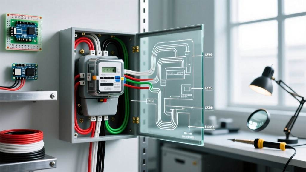

Planning Your Electric Meter Wiring Diagram: The Critical Handoff
Upgrading or installing a new electrical service begins with a precise electric meter wiring diagram. The meter socket (or meter base) serves as the critical handoff point between the utility's distribution grid and your facility's main service panel. In 2026, with the rise of high-draw residential loads like Level 2 EV chargers and heat pumps, proper planning of this junction is more vital than ever. Mistakes in wire sizing, grounding, or socket selection lead to rejected inspections, utility delays, or catastrophic arc flash events.
This installation planning guide breaks down the anatomy of the meter wiring diagram, NEC-compliant conductor sizing, and the exact hardware specifications required for a flawless service upgrade.
Safety Warning: The 'Line' side of the meter socket is ALWAYS energized by the utility grid unless the utility physically disconnects the service drop or lateral. Never attempt to terminate line-side conductors without utility coordination and appropriate arc-flash PPE.
Anatomy of the Electric Meter Wiring Diagram
A standard single-phase, 120/240V residential meter wiring diagram consists of three primary zones:
- The Line Side (Utility Feed): Conductors entering from the overhead service drop or underground service lateral. These terminate on the top or bottom jaws of the meter socket, depending on hub configuration.
- The Metering Mechanism: The utility-owned kilowatt-hour (kWh) meter that slides into the socket's jaws, measuring the voltage drop and current flow across the load.
- The Load Side (Customer Feed): Conductors exiting the socket and routing directly to the Main Service Disconnect (MSD) or Main Breaker Panel. The customer is responsible for sizing, pulling, and terminating these conductors.
Hubbed vs. Hubless Configurations
Your diagram must account for the physical entry point of the utility feed. If you are running an underground service lateral, you must specify a hubless meter socket with a bottom knockout (typically 2-inch to 3-inch). For overhead service drops, you need a hubbed socket with a top threaded hub to accept the service entrance ell (weatherhead conduit).
Meter Socket Selection Matrix
Selecting the correct meter socket ampacity is the first hardware decision. In 2026, 200A is the minimum standard for new single-family homes, while 320A continuous (400A peak) is increasingly common for all-electric homes. Below is a comparison matrix for standard residential and light commercial sockets.
| Ampacity Rating | Voltage | Typical Application | Example Models (2026) | Est. Hardware Cost |
|---|---|---|---|---|
| 100A Continuous | 120/240V 1-Phase | Small additions, older home retrofits, detached garages | Eaton CHMT100L, Square D QOM2100L | $60 - $95 |
| 200A Continuous | 120/240V 1-Phase | Standard modern residential, basic EV charging | Eaton CHMT200L, Square D QOM2200L | $95 - $160 |
| 320A Continuous | 120/240V 1-Phase | Large all-electric homes, dual EV chargers, tankless electric water heaters | Eaton CHMT320L, Siemens W0542L1320 | $250 - $450 |
| 400A Continuous | 120/208V 3-Phase | Light commercial, multi-family residential, small retail | Eaton 1442778, Square D 85389 | $800 - $1,400 |
Note: Always verify with your local utility (e.g., PG&E, Duke Energy, ConEdison) whether they mandate 'Ringless' or 'Ring-Type' sockets. Most modern utilities strictly require ringless designs for tamper resistance and safety.
Conductor Sizing and the NEC 83% Rule
A common error in electric meter wiring diagrams is oversizing the service entrance conductors. According to NFPA 70 (National Electrical Code) Article 310.12, residential dwelling unit service conductors do not need to be sized at 100% of the main breaker rating. Instead, the 83% rule applies.
Sizing for a 200A Service
For a 200A main breaker, the conductors only need an ampacity of 166A (200 x 0.83). Therefore, you can legally and safely use:
- 2/0 AWG Copper (THHN/THWN-2): Rated at 175A in the 75°C column (Table 310.16).
- 4/0 AWG Aluminum (XHHW-2): Rated at 180A in the 75°C column. Aluminum is the industry standard in 2026 due to copper price volatility, saving roughly $400-$600 per service run.
Sizing for a 320A Continuous Service
For a 320A continuous rating (often protected by a 400A main breaker), the 83% rule requires conductors rated for 266A. This mandates:
- 350 kcmil Copper or 500 kcmil Aluminum.
- Due to the stiffness of 500 kcmil aluminum, many installers prefer parallel runs of 2/0 AWG Aluminum (if permitted by the AHJ and utility) or use specialized compression lugs designed for large-gauge wire.
Grounding Electrode System (GES) Design
The meter socket is the central node for your Grounding Electrode Conductor (GEC). Per NEC Article 250.24, the GEC must connect the neutral bus in the main service panel to the Grounding Electrode System. However, many jurisdictions and utilities require a meter socket with a dedicated ground lug to bond the socket enclosure itself to the GES.
GES Specifications for 200A/320A Services
- Ground Rods: Drive two 8-foot, 5/8-inch copper-clad steel ground rods. Space them at least 6 feet apart.
- GEC Wire Size: Per NEC Table 250.66, for 4/0 AWG Aluminum service conductors, a #4 AWG bare copper GEC is required. Do not downsize to #6 AWG unless your service conductors are 1/0 AWG Copper or smaller.
- Water Pipe Bonding: If the building has a continuous underground metallic water pipe, it must be bonded to the GES within the first 5 feet of entry using the same #4 AWG bare copper conductor.
Installation Sequence & Utility Coordination
Executing the electric meter wiring diagram requires strict adherence to the utility's workflow. Out-of-sequence work will result in the utility refusing to set the meter.
The 5-Step Installation Flow
- Mount the Backplate: Secure the meter socket backplate to the exterior wall using 3/8-inch lag screws into structural studs. Ensure the centerline is exactly 60 inches to 66 inches above final grade (standard utility requirement).
- Install Conduit & Weatherhead: Run 2-inch Schedule 80 PVC or EMT conduit from the main panel to the meter socket, and from the meter socket up to the service mast. Install the service entrance ell (weatherhead) pointing downward.
- Pull and Terminate Load-Side: Pull the 4/0 AWG Aluminum conductors from the main panel to the meter socket. Terminate them on the 'Load' jaws using an inch-pound torque screwdriver set to the manufacturer's spec (typically 250-300 in-lbs for 4/0 Al).
- Prepare Line-Side Conductors: Pull the service drop conductors through the weatherhead and into the meter socket. Do NOT terminate them. Coil them neatly inside the socket and tape the ends. The utility lineman will make the final line-side terminations.
- Request Inspection & Meter Set: Call the local AHJ (Authority Having Jurisdiction) for a service rough-in inspection. Once passed, the inspector tags the socket. Call the utility to schedule the 'meter set'. The utility will terminate the line side, slide in the kWh meter, and apply the tamper seal.
Edge Cases & Common Failure Modes
Even with a perfect electric meter wiring diagram, field conditions can introduce edge cases. Be prepared for the following scenarios:
- Rejection for Missing Bypass: For services rated 320A continuous or higher, most utilities mandate a test bypass meter socket. This allows the utility to swap the meter without cutting power to the building. If your diagram specifies a standard non-bypass socket for a 400A service, the utility will reject it.
- Conduit Fill Violations: When pulling 4/0 AWG THHN conductors plus a #4 AWG ground through a 2-inch conduit, you are nearing the 40% conduit fill limit. If you need to pull additional communication or solar PV conductors, you must upgrade to 2.5-inch or 3-inch conduit to comply with NEC Chapter 9, Table 1.
- Seal Ring Interference: When mounting the socket near a corner or adjacent wall, ensure you leave at least 6 inches of clearance on the left side. The utility's locking seal ring requires physical space to be installed and removed; mounting it flush against a corner will result in a failed meter set.
For further reading on modern grid integration and smart metering requirements, refer to the U.S. Department of Energy's Smart Grid guidelines, which outline how modern AMI (Advanced Metering Infrastructure) meters interact with residential service panels. Additionally, consult Eaton's official meter socket catalog for exact dimensional drawings and torque specifications for your specific hardware model.