
The Modern Mandate: Why Your Panel Needs an SPD
If you are pulling permits for a new residential build or upgrading a service in 2026, you are already dealing with the downstream effects of the NEC 2023 mandate (Article 230.67), which requires surge protective devices (SPDs) on all new dwelling unit services. This code cycle has permanently shifted whole-home surge protection from an 'optional upgrade' to a baseline electrical safety requirement. However, simply buying a surge protector and slapping it onto your main breaker panel is a recipe for catastrophic failure. The effectiveness of an SPD relies entirely on the precision of its installation.
Understanding the correct wiring diagram for surge protector integration is critical. A poorly routed wire or an undersized breaker can render a $150 device completely useless during a transient voltage spike. This guide breaks down the exact schematic requirements, physical routing rules, and component specifications for integrating Type 1 and Type 2 SPDs into standard North American split-phase (120/240V) load centers.
Anatomy of the Wiring Diagram for Surge Protector Integration
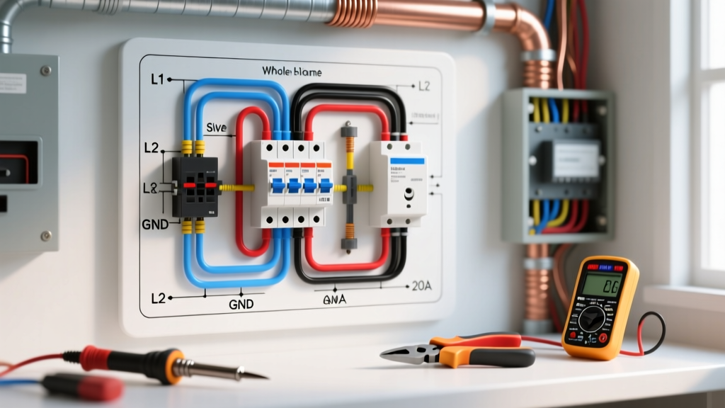
At its core, the wiring diagram for a whole-home Type 2 SPD (the most common panel-mount variety) involves connecting four distinct pathways to your electrical panel's internal architecture. While specific models vary, the universal schematic dictates the following connections:
- Line 1 (Phase A): Routed through a dedicated 2-pole branch breaker.
- Line 2 (Phase B): Routed through the same dedicated 2-pole branch breaker.
- Neutral (Grounded Conductor): Terminated directly on the panel's neutral bus bar.
- Ground (Equipment Grounding Conductor): Terminated directly on the panel's ground bus bar (or combined neutral/ground bar in main service panels).
CRITICAL INSTALLATION RULE: Never wire an SPD to the load side of an existing branch circuit breaker that also feeds receptacles or lighting. The SPD must have a dedicated overcurrent protection device (OCPD) to isolate it from the rest of the home's wiring in the event of an internal short or thermal runaway.
SPD Classification Matrix: Choosing the Right Device
Before interpreting the wiring diagram, you must select the correct UL 1449 listed device for your point of connection. The National Electrical Code (NEC) and IEEE Standard 1100 categorize SPDs by their physical installation location and surge current capacity.
| Type | Installation Point | Primary Use Case | Example Model (2026 Market) | Avg. Cost |
|---|---|---|---|---|
| Type 1 | Line side of service disconnect (utility side) | Direct lightning protection; service entrance | Leviton 51120-1 | $180 - $250 |
| Type 2 | Load side of service disconnect (breaker panel) | Standard whole-home retrofit & new builds | Eaton CHSPT2ULTRA | $110 - $140 |
| Type 3 | Point of utilization (receptacle level) | Sensitive electronics, point-of-use backup | Tripp Lite TLP1210SATG | $40 - $70 |
| Type 4 | Internal component level (PCB mount) | Industrial equipment, internal appliance boards | Littelfuse TMOV Series | N/A (OEM) |
Step-by-Step Panel Integration: Eaton vs. Siemens Schematics
The physical wiring diagram changes drastically depending on whether you are using a traditional wire-lead SPD or a bus-bar integrated SPD. Let us examine the two dominant architectural approaches in the 2026 residential market.
Approach A: Traditional Wire-Lead SPD (Eaton CHSPT2ULTRA)
The Eaton CHSPT2ULTRA is a 100kA Type 2 SPD designed for universal panel compatibility (BR, CH, QO, Homeline). The wiring diagram requires you to install a dedicated 2-pole 50A breaker.
- Breaker Sizing: Install a 2-pole 50A breaker as close to the main service disconnect as possible. This minimizes the distance to the neutral bar.
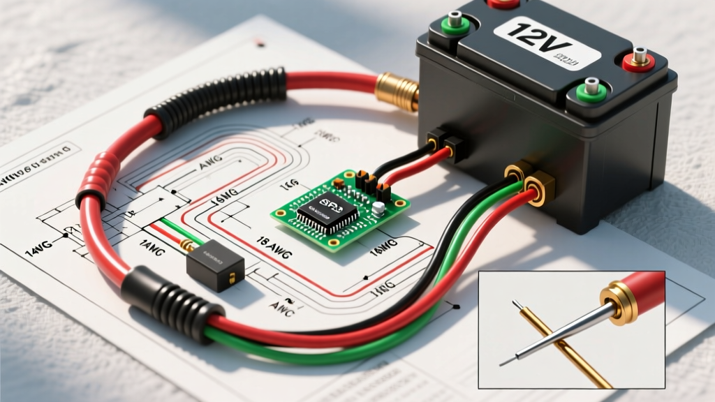
- Wire Gauge: The manufacturer specifies a minimum of 10 AWG stranded copper. However, for runs exceeding 18 inches, upgrade to 8 AWG to reduce impedance and voltage drop during a transient event.
- Routing: Cut the factory leads to the exact length needed. Do not coil excess wire inside the panel.
- Termination: Connect the black and red leads to the 2-pole breaker. Land the white (neutral) and green (ground) wires on their respective bus bars, torquing the set screws to the manufacturer's specification (typically 35 to 45 in-lbs for standard neutral bars).
Approach B: Bus-Bar Integrated SPD (Siemens QSA2020SPD)
Siemens engineered the QSA2020SPD to eliminate the most common point of failure in SPD wiring diagrams: the hot lead wires. This unit plugs directly onto the panel's bus stab just like a standard breaker.
- Internal OCPD: The unit features two integrated 20A breakers that clip onto the hot bus stabs. No external hot wires are required.
- Wiring Diagram Simplification: You only need to route the 10 AWG white neutral wire and the bare/green ground wire to the panel's bus bars.
- Space Constraints: Requires two full 1-inch spaces on the panel bus bar. It cannot be used in panels with half-space rejection clips (CTL panels) unless specifically listed for it.
The Physics of Lead Length: Why the '6-Inch Rule' Matters
The most critical, yet frequently ignored, aspect of the wiring diagram for surge protector installation is lead length. According to the National Fire Protection Association (NFPA) and best practices outlined by major manufacturers, the total length of the conductors connecting the SPD to the panel (from the breaker lugs to the SPD, and from the SPD to the ground/neutral bars) should be kept as short as possible, ideally under 6 inches.
Why? The Inductance Penalty.
Wire has inherent inductance. When a high-frequency, fast-rising transient surge (like a lightning-induced spike with an 8/20 microsecond waveform) hits the wire, the inductance creates a massive voltage drop across the wire itself. The formula for this voltage drop is V = L (di/dt).
For every additional inch of wire beyond the optimal short path, you can add roughly 100 volts of let-through voltage to your home's electronics. If your SPD is rated to clamp at 400V, but you use 30 inches of coiled, loosely routed wire, the inductance could push the actual let-through voltage to 1,200V or higher, completely defeating the purpose of the device and destroying the appliances you intended to protect.
Routing Best Practices for Minimal Inductance
- Keep Leads Together: Route the hot, neutral, and ground wires parallel to each other and tight against the panel wall. This minimizes the loop area, which directly reduces total inductance.
- No Sharp Bends: Avoid 90-degree right-angle bends. Use sweeping, gradual curves to prevent stress on the wire and maintain optimal electron flow during a high-frequency event.
- Avoid the 'Daisy Chain': Never connect the SPD ground to a downstream ground bar that is daisy-chained back to the main ground bar. Land it directly on the main grounding bus bar or the primary grounding electrode conductor (GEC) lug if accessible and listed for dual conductors.
Troubleshooting and Failure Modes
Even with a perfect wiring diagram, SPDs can fail. Modern Type 2 SPDs use Metal Oxide Varistors (MOVs) paired with Thermal Disconnects (TDs). Understanding how these fail is crucial for maintenance.
1. Thermal Runaway and the Indicator Light
MOVs degrade slightly every time they clamp a surge. Over time, their leakage current increases, generating heat. If the heat exceeds the threshold of the internal thermal fuse, the fuse melts, physically disconnecting the MOV from the circuit to prevent a panel fire. When this happens, the external LED indicator on the SPD will turn off. Action: If the light is off, the device is dead and must be replaced immediately. It offers zero protection.
2. NEMA Enclosure Degradation (Outdoor Type 1s)
If you are wiring a Type 1 SPD on the exterior of the home (line-side of the meter socket), ensure the enclosure is rated NEMA 4X. Standard NEMA 3R enclosures will allow wind-driven rain and UV degradation to compromise the internal potting compound over a 5-to-7-year period, leading to moisture ingress and catastrophic short circuits.
Verifying the Grounding Electrode System (GES)
A surge protector does not 'absorb' excess energy; it diverts it to ground. Therefore, the wiring diagram for your surge protector is only as effective as your home's Grounding Electrode System. Before installing an SPD, verify that your panel has a low-impedance path to earth. This typically requires two 5/8-inch copper-clad ground rods driven 8 feet deep and spaced at least 6 feet apart, or a continuous Ufer ground (concrete-encased electrode). For comprehensive grounding standards, always consult Eaton's surge protection application guides and local utility requirements, as poor soil resistivity can severely bottleneck an SPD's clamping performance.
Summary Checklist for the Electrician or Advanced DIYer
- Verify panel bus bar compatibility (CTL vs. Non-CTL).
- Install dedicated 2-pole OCPD (50A for traditional, integrated for bus-stab models).
- Use 10 AWG minimum (8 AWG preferred) stranded copper.
- Trim leads to exact length; keep total wire run under 18 inches, ideally under 6 inches.
- Torque all neutral and ground bus bar screws to manufacturer specifications (use a calibrated inch-pound torque screwdriver).
- Verify main GES integrity before energizing.