
The Ultimate Wiring Diagram for Ford 8N 12 Volt Conversion
The Ford 8N tractor, produced between 1947 and 1952, is one of the most iconic and widely restored agricultural machines in history. Out of the factory, these tractors were equipped with a 6-volt, positive-ground electrical system. While adequate for the 1940s, modern electrical demands—such as high-output halogen work lights, electronic ignition modules, and 12-volt accessory chargers—require a system upgrade. Treating the tractor’s electrical network as a heavy-duty electromechanical appliance, this tutorial provides a comprehensive, node-to-node wiring diagram for Ford 8N 12 volt conversions, shifting the system to a modern 12-volt, negative-ground architecture.
Safety Directive: Before cutting, crimping, or routing any wire, disconnect the ground cable from the battery. A short circuit in an un-fused 8N main harness can instantly melt 10 AWG wire and ignite the tractor’s wiring loom.
Core Component Selection for the 12V Upgrade
Before executing the wiring diagram, you must source the correct 12-volt components. Attempting to run original 6-volt components on a 14.4-volt alternator output will result in immediate catastrophic failure of the bulbs, coil, and starter.
1. The Alternator: Delco 10-SI (1-Wire)
The industry standard for the Ford 8N 12-volt conversion is the Delco 10-SI 1-wire alternator (typically rated at 63 to 94 amps). Unlike the original 6-volt generator, which required a complex voltage regulator and three separate wires, the 10-SI alternator features an internal regulator. It requires only a single heavy-gauge wire from the alternator’s BAT terminal to the battery side of the ammeter or starter solenoid. In 2026, a remanufactured 10-SI alternator costs between $65 and $95 at most agricultural supply stores.
2. Ignition Coil and Ballast Resistor
The Ford 8N utilizes a front-mount distributor. You have two choices for the ignition coil:
- Option A (Retain 6V Coil): Keep the original 6-volt coil but wire a 1.2 to 1.5-ohm ceramic ballast resistor in series on the positive feed wire. This drops the 14.4V alternator output down to a safe ~7V at the coil, preventing the breaker points from burning out.
- Option B (12V Internal Resistor Coil): Purchase a dedicated 12-volt coil (e.g., NAPA IC14SB or equivalent). These have an internal resistor and wire directly to the ignition switch without an external ballast.
3. Starter Motor Considerations
Applying 12 volts to the original 6-volt starter motor will cause it to spin at twice its designed RPM. While this provides cranking power, it frequently causes the Bendix drive to over-engage, shearing teeth off the flywheel ring gear. For a permanent, reliable appliance-level wiring setup, upgrade to a dedicated 12-volt starter (Part # 8N-11002-A12, approx. $120-$150). If you must retain the 6V starter temporarily, limit cranking to strictly under 5 seconds per attempt.
Step-by-Step Wiring Diagram & Routing Sequence
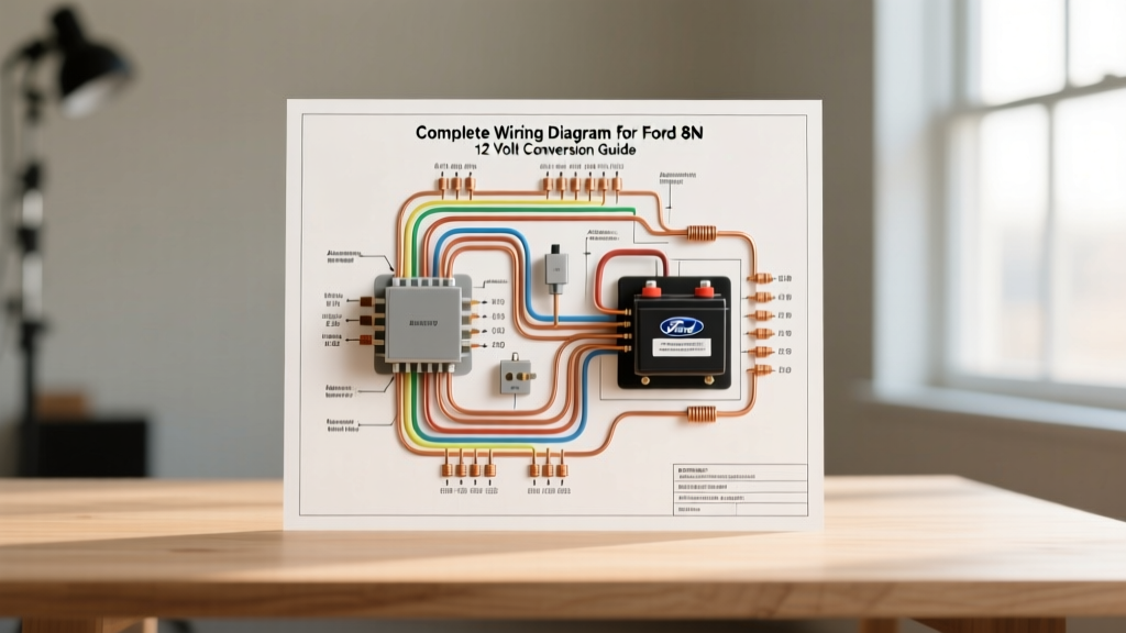
Because schematic images cannot be dynamically rendered in this text format, the following sequence serves as your exact wiring diagram for Ford 8N 12 volt architecture. Follow these node-to-node connections precisely.
- Battery Ground to Chassis: Connect the negative (-) terminal of the new 12V battery to the tractor’s chassis or transmission housing using a 2/0 AWG braided ground strap. Clean the mounting point to bare metal to ensure zero resistance.
- Battery Positive to Solenoid: Run a 2/0 AWG red cable from the positive (+) battery terminal to the battery-side lug of the starter solenoid (mounted on the firewall or dash support).
- Solenoid to Ammeter: Run a 10 AWG red wire from the battery-side lug of the solenoid to the positive (+) post on the back of the ammeter. Note: The original 8N ammeter was wired for positive ground. To make it read correctly on a negative ground system, you must swap the two wires on the back of the ammeter gauge.
- Ammeter to Alternator & Main Harness: From the negative (-) post on the back of the ammeter, run a 10 AWG red wire. Create a junction (using a heavy-duty terminal block or solder-seal heat shrink). One branch goes directly to the BAT terminal on the Delco 10-SI alternator. The other branch feeds the main ignition switch and lighting circuits.
- Ignition Switch to Coil: Run a 14 AWG wire from the ignition switch output terminal. If using a 6V coil, route this wire through the ceramic ballast resistor, then to the positive (+) terminal on the coil. If using a 12V coil, route directly to the positive (+) terminal.
- Coil to Distributor: Run a 14 AWG wire from the negative (-) terminal on the coil to the single terminal post on the front-mount distributor.
- Starter Solenoid Trigger: Wire the push-button starter switch (located on the dash) to ground the solenoid trigger terminal, engaging the starter motor.
Wire Gauge and Termination Matrix
Adhering to SAE J1128 standards for low-tension primary cable is critical in high-vibration agricultural environments. Undersized wire will cause voltage drop, resulting in weak spark and dim lights.
| Circuit Path | Wire Gauge (AWG) | Insulation Type | Termination Method |
|---|---|---|---|
| Battery (-) to Chassis | 2/0 AWG | Braided Copper / PVC | Heavy Lug, Bolted to bare metal |
| Battery (+) to Solenoid | 2/0 AWG | THHW / Cross-linked PE | Heavy Lug, Heat-shrink sealed |
| Solenoid to Ammeter / Alt | 10 AWG | SGT (Stranded) | Ring terminal, mechanical crimp |
| Ignition Switch to Coil | 14 AWG | GXL (Thin-wall) | Spade terminal or solder-seal |
| Lighting Circuits | 14 AWG (12 AWG for Halogen) | GXL / SXL | Weather-pack connectors |
Common Failure Modes and Troubleshooting
Even with a perfect wiring diagram for Ford 8N 12 volt conversions, field conditions introduce variables. Here are the most common failure modes encountered by restorers and how to diagnose them.
Parasitic Draw from the 1-Wire Alternator
The Issue: The Delco 10-SI is a "self-exciting" alternator. It requires the engine to reach roughly 1,200 RPM to "turn on" and begin charging. If the internal diode trio fails, the alternator can back-feed current to ground when the tractor is off, draining the battery overnight.
The Fix: Use a digital multimeter to test for parasitic draw. Disconnect the negative battery cable and place the multimeter in series (Amps mode) between the cable and the battery post. A healthy system should read under 0.05A. If it reads 2A to 5A, the alternator diodes are fried. Replace the alternator or install a manual dash-mounted disconnect switch.
Ignition Points Burning Out Prematurely
The Issue: If you retained the 6V coil but forgot the ballast resistor (or the resistor failed short), the full 14.4V is hitting the 6V coil. This causes excessive current through the distributor points, melting the tungsten contacts within hours of operation.
The Fix: Measure the voltage at the coil positive terminal with the engine running. It should read between 6.5V and 8.5V. If it reads 13V+, immediately shut down the engine and verify the ballast resistor is wired in series and measuring 1.2 to 1.5 ohms.
Ammeter Reading Discharge While Running
The Issue: The tractor is charging, but the dash ammeter shows a deep discharge.
The Fix: This is almost exclusively caused by failing to reverse the ammeter posts during the positive-to-negative ground swap. Simply swap the two 10 AWG wires on the back of the gauge. Do not attempt to flip the gauge face or magnet, as this will ruin the calibration.
Authoritative References & Further Reading
For continued maintenance, parts sourcing, and community troubleshooting regarding Ford N-Series tractors, consult the following authoritative archives:
- Yesterday's Tractors (YT) - The premier global database and forum for antique tractor restoration, featuring extensive technical threads on 8N 12-volt conversion edge cases.
- The N Tractor Club - Dedicated exclusively to Ford 9N, 2N, and 8N tractors, providing OEM specification sheets and verified vendor lists for 12-volt starter upgrades.
- SAE International (J1128) - The definitive standard for automotive primary cable sizing, ensuring your wire gauge selections meet modern thermal and voltage-drop tolerances.