
Decoding the Wiring Diagram for a Goodman Furnace
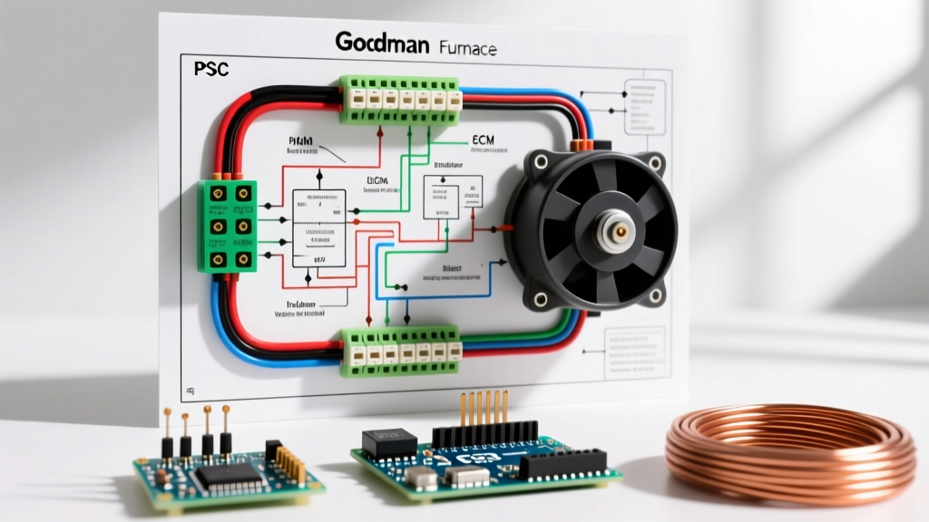
Locating and interpreting the wiring diagram for a Goodman furnace is the critical first step before attempting any HVAC motor replacement or control board troubleshooting. Whether you are working on a legacy GMSS96 gas furnace with a traditional PSC (Permanent Split Capacitor) blower or a newer GC9C96 modulating unit featuring an advanced ECM (Electronically Commutated Motor), the schematic is your roadmap. With the 2026 Department of Energy (DOE) efficiency standards now in full effect, understanding the transition from fixed-speed to variable-speed motor wiring is essential for any DIY enthusiast or HVAC technician.
According to the U.S. Department of Energy, modern high-efficiency furnaces rely heavily on ECM technology to reduce electrical consumption by up to 75% compared to older PSC motors. However, the wiring complexity increases significantly. This guide breaks down the motor-specific circuits found on Goodman schematics, focusing on the blower motor, the draft inducer motor, and the central control board.
Safety Warning: Before opening the blower compartment or touching any terminals, disconnect the 120V/240V main power supply at the breaker panel and use a Lockout/Tagout (LOTO) procedure. Capacitors can hold a lethal charge even when power is removed. Always verify zero voltage with a CAT III multimeter.
Anatomy of the Goodman Furnace Schematic
Goodman typically affixes the wiring diagram to the inside of the lower blower access door. The schematic is divided into two primary voltage sections:
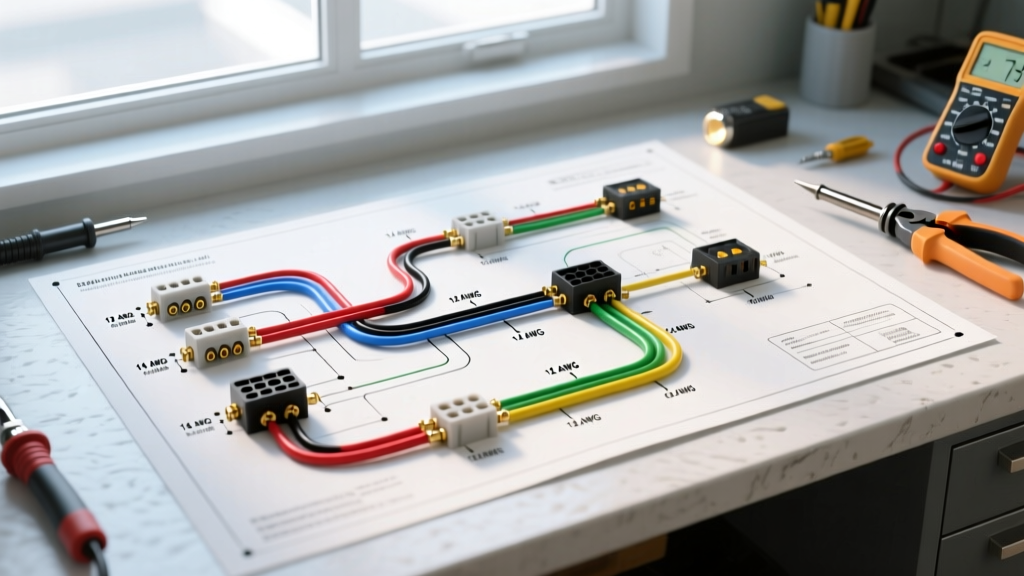
- Line Voltage (120VAC): Powers the blower motor, draft inducer motor, and igniter. Represented by thicker lines and typically utilizes 14 AWG or 12 AWG wire.
- Low Voltage (24VAC): Powers the control board logic, thermostat signals, and gas valve. Represented by thinner lines and utilizes 18 AWG stranded wire.
Key Control Board Terminals (B1859032 & 0130M00001S)
The control board is the brain of the furnace. When wiring motors, you will interact primarily with these terminals:
- HEAT (or H): Supplies 120V to the blower motor's heating speed tap.
- COOL (or C): Supplies 120V to the blower motor's cooling speed tap.
- INDUCER (or IND): Supplies 120V to the draft inducer motor to purge the heat exchanger before ignition.
- NEUTRAL (N): The common return path for all 120V motor circuits.
Wiring the PSC Blower Motor (4-Speed Configuration)
Older Goodman models and specific replacement scenarios still utilize PSC blower motors. These motors require a run capacitor (typically 5+5 MFD or 7.5+7.5 MFD at 370VAC) and feature a 4-speed tap configuration. The wiring diagram for a Goodman furnace with a PSC motor will show four distinct colored wires originating from the motor peckerhead.
Standard Goodman PSC Speed Taps and Applications
| Wire Color | Speed Tap | Typical Application | Control Board Terminal |
|---|---|---|---|
| Black | High (100%) | Air Conditioning (Cooling) | COOL |
| Blue | Medium-High (75%) | High-Stage Heating / 90% CFM | HEAT (or PARK) |
| Red | Medium-Low (50%) | Low-Stage Heating / 60% CFM | HEAT |
| White | Low (25-30%) | Continuous Fan Circulation | PARK (Unused) |
Crucial Wiring Rule: Never leave an unused speed tap wire exposed or resting against the metal chassis. According to NFPA 70 (National Electrical Code) Article 430, all motor conductors must be properly terminated or insulated. Unused PSC taps must be wrapped in electrical tape and secured, or plugged into the designated 'PARK' spade terminal on the motor capacitor bracket to prevent a dead short that will instantly destroy the control board's 5-amp blade fuse.
Wiring the ECM Blower Motor (Genteq X13 / Broad Ocean)
As of 2026, nearly all new Goodman furnaces ship with ECM motors. The wiring diagram for a Goodman furnace equipped with an ECM motor looks vastly different. There are no speed taps. Instead, the motor receives constant 120V line voltage and uses a low-voltage communication harness to determine speed based on control board logic.
ECM Connection Breakdown
- High Voltage Harness (3-Pin): Connects Line (120V), Neutral, and Ground directly from the control board's line voltage distribution block. This provides constant power to the motor's internal microprocessor.
- Low Voltage Harness (5-Pin): Connects to the control board's ECM terminal block. The pins correspond to 24VAC signals:
- R: 24V Reference
- C: 24V Common
- G: Fan Only signal
- W: Heat signal
- Y: Cool signal
Information Gain - Tonnage Selection: Unlike PSC motors where you change physical wire taps to adjust airflow, ECM motors require you to set the physical tonnage or CFM profile on the motor end-bell. On a Broad Ocean ECM used in Goodman units, this is done via a rotary dial or a series of jumper pins (e.g., setting the dial to '03' for a 3-ton system). If you are replacing a motor and skip this step, the furnace will likely fault out on a High Limit Switch due to insufficient airflow across the heat exchanger.
The Draft Inducer Motor Circuit
The draft inducer motor is a small, 120V shaded-pole or PSC motor mounted on the collector box. Its job is to create a negative pressure draft to pull combustion gases through the heat exchanger and out the flue.
Inducer Wiring and Pressure Switch Interlock
The wiring diagram will show the inducer motor wired in parallel with the pressure switch circuit. The control board sends 120V to the inducer via a 2-pin Molex connector. Once the motor reaches full RPM (typically drawing between 0.7 and 1.2 Amps), it creates enough vacuum to close the pressure switch. The closed pressure switch sends a 24V signal back to the board's 'PS' or 'PRES' terminal, proving the draft is established before the board allows the hot surface igniter to glow.
Common Failure Mode: If the inducer motor hums but does not spin, do not immediately assume the motor is dead. Check the external run capacitor (if equipped, usually 1 or 2 MFD). More commonly, the Molex connector pins become oxidized or loose due to furnace vibration, causing a voltage drop. Unplug the connector, inspect for arcing marks, and crimp the female terminals tighter with needle-nose pliers before replacing the $150+ motor assembly.
Troubleshooting Motor Wiring Faults
When the wiring diagram for a Goodman furnace points to a motor circuit failure, use this systematic approach to isolate the issue:
1. The 5-Amp Fuse Blowout
If the 5-amp automotive blade fuse on the Goodman control board (usually purple or orange) is blown, it is rarely the blower motor's fault. The blower runs on 120V; the fuse protects the 24V secondary circuit. A blown fuse indicates a short in the 18 AWG thermostat wiring, a shorted outdoor AC contactor coil, or a pinched wire rubbing against the metal chassis. Disconnect the thermostat wires at the board and use a multimeter's continuity setting to check for shorts between 'R' and 'C'.
2. Blower Motor Won't Start (PSC)
- Test the Capacitor: Use a multimeter with a capacitance setting. A 7.5 MFD capacitor should read within 6% (7.05 to 7.95 MFD). If it reads low or is bulging, replace it.
- Ohm the Windings: Disconnect power and remove the motor wires. Measure resistance between the White (Common) and Black (High) wires. You should see a reading between 5 and 15 ohms. An 'OL' (Open Line) reading indicates a broken internal winding, requiring motor replacement.
3. ECM Motor Flash Codes
Goodman ECM motors feature an LED diagnostic light on the motor belly. If the motor fails to start, count the flashes. For example, on the Broad Ocean X13, 2 Flashes typically indicates a missing 24V signal from the control board, while 4 Flashes indicates an internal microprocessor fault. Refer to the official Goodman product documents for the exact flash code matrix corresponding to your specific motor model number.
Final Thoughts on Furnace Motor Wiring
Mastering the wiring diagram for a Goodman furnace requires respecting the boundary between high-voltage power delivery and low-voltage logic control. Whether you are terminating 14 AWG line wires to an ECM harness or mapping out the speed taps on a legacy PSC blower, precision is paramount. Always verify your wire gauges, ensure all unused taps are safely parked, and rely on the schematic taped to the blower door rather than memory. By adhering to NEC standards and understanding the specific operational logic of Goodman control boards, you can safely diagnose, replace, and optimize your furnace motor systems.