
Planning Your Kenmore Dryer Installation
Installing a heavy appliance like a clothes dryer requires more than just plugging it into a wall. For DIYers and electricians alike, understanding the specific wiring diagram for a Kenmore dryer is the cornerstone of a safe, code-compliant installation. According to the Consumer Product Safety Commission (CPSC), improper electrical connections and neglected exhaust venting are leading causes of residential appliance fires. Planning your electrical rough-in and final termination before unboxing the unit prevents costly rework and mitigates shock hazards.
This installation planning guide breaks down the electrical requirements, terminal block configurations, and schematic interpretations necessary for Kenmore electric and gas models. As of 2026, with copper prices fluctuating and local jurisdictions strictly enforcing the latest National Electrical Code (NEC) updates, precise planning is more critical than ever.
The Secret Behind Kenmore Model Numbers
Before consulting a schematic, you must identify the original equipment manufacturer (OEM). Kenmore does not manufacture its own appliances; the brand is a private label sold by Sears. The first three digits of your Kenmore dryer’s model number dictate the internal wiring architecture:
- 110. Prefix: Manufactured by Whirlpool. These units typically use a standardized Whirlpool terminal block, motor relay, and heating element circuit. The wiring diagrams are highly consistent across the Kenmore 800, 90, and Elite series.
- 103. Prefix: Manufactured by Frigidaire/Electrolux. These models feature different electronic control boards and thermistor layouts, requiring a completely different schematic approach.
- 106. Prefix: Also manufactured by Whirlpool, but often designated for specific retail configurations or older legacy models.
Knowing your prefix allows you to source the correct replacement pigtails and accurately trace continuity paths on the wiring diagram.
Circuit Sizing and Receptacle Planning
Electric Kenmore dryers operate on a 240-volt, 30-amp dedicated circuit. The NEC mandates that continuous loads cannot exceed 80% of a breaker's rating, but a standard residential dryer is not classified as a continuous load. Therefore, a 30-amp double-pole breaker paired with 10 AWG copper wire is the universal standard.
The 3-Prong vs. 4-Prong Receptacle Dilemma
If you are upgrading an older home, you will likely encounter a NEMA 10-30R (3-prong) receptacle. The National Fire Protection Association (NFPA) and the NEC (Article 250.140) phased out 3-prong dryer outlets in new construction in 1996 to separate the neutral and ground paths. However, existing 3-prong setups are grandfathered in.
| Feature | NEMA 10-30R (3-Prong) | NEMA 14-30R (4-Prong) |
|---|---|---|
| Wire Configuration | Hot, Hot, Neutral (No dedicated ground) | Hot, Hot, Neutral, Dedicated Ground |
| Cable Type | 10/2 NM-B with bare ground (older SE cable) | 10/3 NM-B (Red, Black, White, Bare) |
| Neutral-to-Ground Bond | Required at the dryer terminal block | Strictly prohibited at the dryer |
| 2026 Install Cost (Avg) | $15 - $25 (Receptacle only) | $45 - $85 (Receptacle + 10/3 wire per ft) |
NEC Code Alert: If you are installing a new circuit in 2026, you must install a 4-prong NEMA 14-30R receptacle. You cannot legally install a new 3-prong outlet for a dryer, even in a renovation.
Decoding the Terminal Block Wiring Diagram
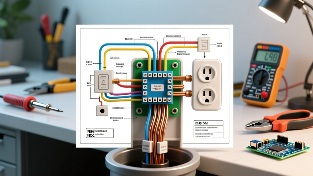
The terminal block is where the external power cord meets the dryer’s internal wiring harness. On a standard Whirlpool-built Kenmore (110. prefix), the terminal block is located behind a small access panel on the lower rear of the unit.
4-Prong Terminal Connection Steps
When using a 4-prong pigtail, the wiring diagram dictates a strict separation of current-carrying and grounding conductors:
- L1 (Left Outer Terminal): Connect the Red wire (or Black, depending on cord color coding). This supplies 120V for the motor and controls.
- Neutral (Center Terminal): Connect the White wire. This carries the unbalanced current back to the panel. Crucial: The internal dryer neutral harness must also be attached here.
- L2 (Right Outer Terminal): Connect the Black wire. Combined with L1, this provides the 240V required for the heating element.
- Ground (Green Ground Screw): Connect the Green wire to the dedicated grounding screw on the dryer chassis, not the terminal block.
The Grounding Strap: A Critical Safety Step
The most common and dangerous mistake DIYers make when transitioning from a 3-prong to a 4-prong cord is failing to remove or fold back the neutral-to-ground bonding strap. On a 3-prong setup, this metal strap connects the center neutral terminal to the dryer chassis.
If you plug a 4-prong cord into a dryer with the bonding strap still in place, the neutral current will flow back to the panel via both the neutral wire and the ground wire. This creates a parallel path, which can cause nuisance tripping on modern AFCI/GFCI breakers and energize the dryer chassis if the ground wire fails. Always remove the bonding strap and tuck it away when using a 4-prong cord.
Interpreting the Schematic: Key Components
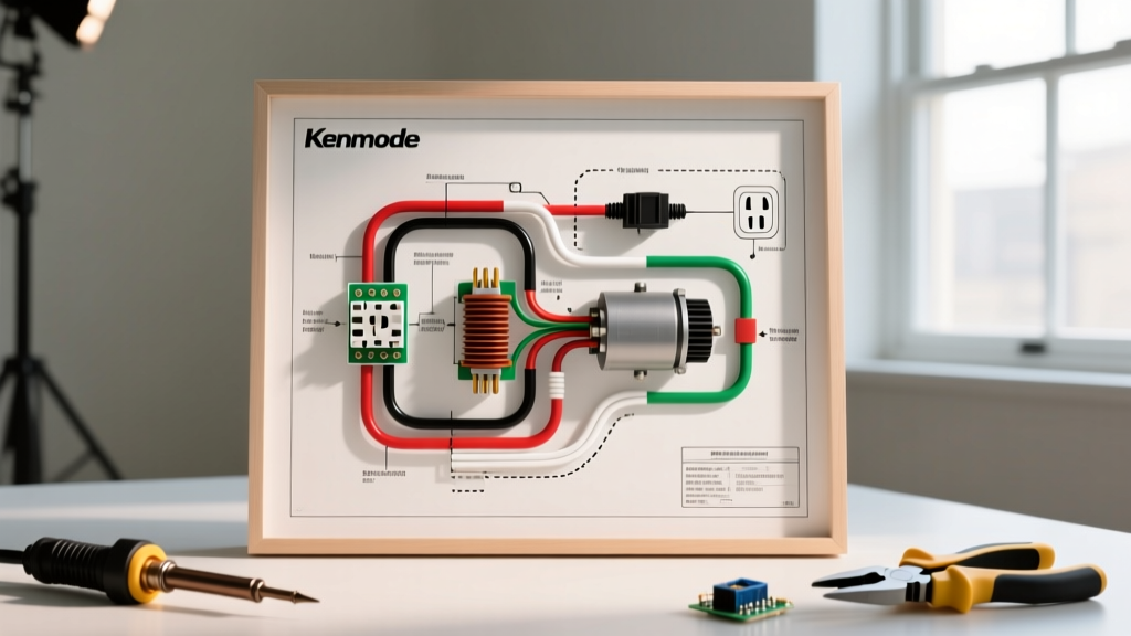
A full wiring diagram for a Kenmore dryer extends beyond the terminal block. It maps the 120V control circuits and the 240V heating circuits. When planning your installation or troubleshooting a unit that won't start, look for these specific nodes on the schematic:
- Thermal Fuse: Located on the blower housing. The diagram will show it in series with the motor relay. If this blows due to restricted venting, the entire 120V control circuit dies.
- Cycling Thermostat & High-Limit Thermostat: These regulate the heating element. The wiring diagram will show them interrupting the L1 or L2 feed to the element.
- Centrifugal Motor Switch: Found inside the drive motor assembly. The diagram illustrates how this switch engages the heating element circuit only when the motor reaches operational RPM, preventing the element from heating if the blower fails.
- Electronic Control Board (Elite Models): Modern Kenmore Elite dryers replace mechanical timers with PCBs. The schematic will show low-voltage DC outputs to relays and thermistor inputs rather than direct 240V routing.
Common Installation Failure Modes
Even with the correct wiring diagram, execution errors lead to specific failure modes. Understanding these edge cases is vital for installation planning:
1. Reversed Polarity on Gas Models
If you are installing a Kenmore gas dryer, it requires a standard 120V, 15-amp or 20-amp NEMA 5-15R or 5-20R receptacle. The wiring diagram for a gas model is entirely different, utilizing a 12 AWG, 2-wire cable with a ground. If the hot and neutral are reversed at the receptacle, the control board may power on, but the gas valve solenoids and igniter circuit will fail to operate correctly, posing a severe carbon monoxide risk.
2. Voltage Drop on Long Runs
If your electrical panel is located more than 75 feet from the dryer receptacle, 10 AWG wire may experience excessive voltage drop, causing the heating element to underperform and the motor to overheat. For runs exceeding 75 feet, upgrade to 8 AWG copper wire and use a 40-amp breaker with a 30-amp fuse at the disconnect, or consult a licensed electrician to adjust the breaker sizing per NEC Table 310.16.
3. Loose Terminal Block Connections
The terminal block screws must be torqued securely. A loose neutral connection on the center terminal will cause 120V control components (like the timer and motor) to receive fluctuating voltage, often resulting in melted wire insulation and catastrophic control board failure.
2026 Material and Tool Checklist
Proper planning requires having the right materials on site before beginning the rough-in or final hookup. Budget for the following 2026 market rates:
- 30A Double-Pole Breaker: $15 - $25 (Ensure it matches your panel brand, e.g., Square D Homeline or Siemens).
- 10/3 NM-B Romex Cable: $1.50 - $2.50 per foot (Prices remain elevated due to global copper demand).
- NEMA 14-30R Receptacle: $12 - $18 (Leviton or Bryant residential grade).
- 4-Prong Dryer Pigtail (6ft): $15 - $25 (Ensure it is UL-listed with a molded strain relief clamp).
- Foil-Backed Exhaust Ducting: $20 - $35 (Rigid aluminum is required by code; never use flexible plastic or foil-only ducts).
- Tools: Wire strippers (10-14 AWG), torque screwdriver, multimeter for continuity testing, and a 1/4-inch nut driver for the terminal block.
Final Verification
Before pushing the dryer into its final position, turn on the 30-amp breaker and use a multimeter to verify the voltage at the receptacle. You should read exactly 240V across L1 and L2, and 120V from L1 to Neutral, L2 to Neutral, L1 to Ground, and L2 to Ground. Once verified, plug in the unit, run a timed dry cycle for 10 minutes, and monitor the terminal block access panel for any signs of arcing or unusual heat. By strictly adhering to the wiring diagram and NEC guidelines, your Kenmore dryer installation will be safe, efficient, and built to last.