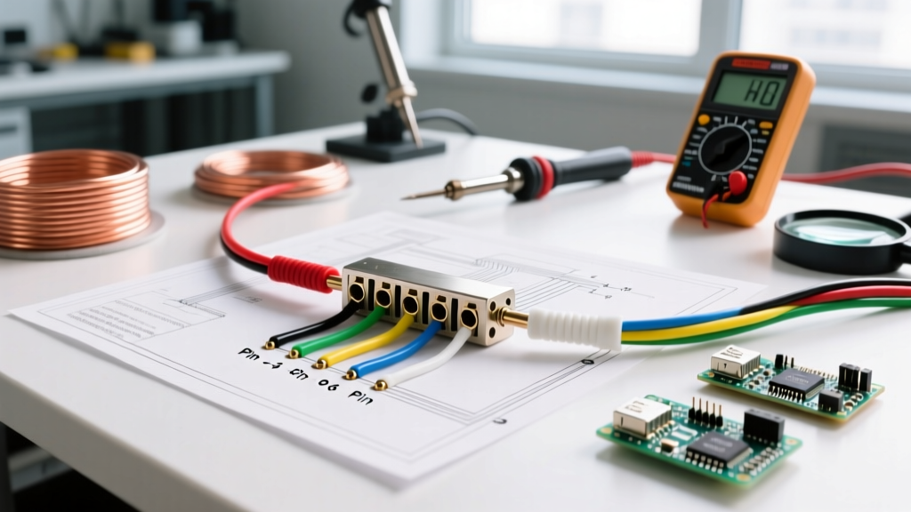

The Anatomy of the 6-Way Round Connector
When dealing with medium-duty trailers, vintage Airstreams, and heavy agricultural equipment, the 6-way round connector remains an industry staple. Unlike the more common 7-way RV blade, the wiring diagram for 6 pin trailer connector setups relies on a circular arrangement with a single center pin. While it looks straightforward, this connector is notorious for cross-wiring issues, primarily due to competing industry standards. As of 2026, the most common failure points we see in the field involve severe voltage drop on the electric brake circuit and catastrophic ground loop failures caused by improper ring terminal crimps.
To effectively troubleshoot, you must first understand that there is no single universal standard for the 6-pin round plug. The two dominant configurations are the RV Standard and the Agricultural/Tractor Standard. Misidentifying which standard your tow vehicle and trailer are wired to is the number one cause of locked-up trailer brakes or blown auxiliary fuses.
Standard RV vs. Agricultural Pinouts
Below is the definitive pinout matrix comparing the two primary wiring standards. The physical plug (such as the widely used CURT 58160) remains identical, but the internal wire routing changes drastically.
| Pin Position | Wire Color (Typical) | RV Standard Function | Ag/Tractor Standard Function |
|---|---|---|---|
| 1 (Outer) | White | Ground (Chassis) | Ground (Chassis) |
| 2 (Outer) | Black / Red | 12V Auxiliary / Battery Charge | Electric Brakes |
| 3 (Outer) | Yellow | Left Turn / Stop | Left Turn / Stop |
| 4 (Outer) | Green | Right Turn / Stop | Right Turn / Stop |
| 5 (Outer) | Brown | Tail / Clearance / Running | Tail / Clearance / Running |
| 6 (Center) | Blue | Electric Brakes | 12V Auxiliary / Battery Charge |
Reference: For comprehensive industry standards on trailer connectors, consult the SAE J286 standard documentation which governs heavy-duty and commercial trailer wiring configurations.
The "Center Pin" Trap: Why Your Brakes Lock Up
The most dangerous edge case when using a wiring diagram for 6 pin trailer connector layouts is the center pin swap. If your tow vehicle is wired to the RV standard (Center Pin = Brakes) and your trailer is wired to the Ag standard (Center Pin = 12V Aux), applying the tow vehicle's brakes will send 12V continuous power to the trailer's auxiliary circuit. Conversely, the trailer's brake controller output will hit the tow vehicle's auxiliary battery charge line.
Expert Troubleshooting Tip: If you plug in the trailer and the electric brakes immediately lock up without touching the brake pedal, do not assume the brake controller is defective. You are almost certainly experiencing a center-pin standard mismatch. Swap the blue and black wires at the trailer junction box to resolve this instantly.
Step-by-Step Multimeter Troubleshooting Protocol
Throwing parts at a trailer lighting issue is a waste of time and money. Grab a True RMS multimeter (like the Fluke 117) and follow this systematic diagnostic flow to isolate the fault.
Step 1: The Ground Loop Voltage Drop Test
Over 70% of trailer wiring faults are ground-related. A bad ground forces return current to backfeed through the tail light filaments, causing lights to dim when brakes are applied.
- Set your multimeter to DC Volts. Connect the black probe to the tow vehicle's clean, bare chassis (not the plug ground).
- Connect the red probe to Pin 1 (White/Ground) on the trailer side plug while the running lights and brake lights are actively engaged.
- Read the voltage. A healthy ground will show less than 0.1V. If you read 0.5V or higher, you have a high-resistance ground. Strip the white wire, sand the chassis to bare metal, and install a new ring terminal using a 5/16" stainless steel bolt and a star lock washer.
Step 2: Load-Testing the Electric Brake Circuit
Testing the brake circuit with a simple test light is insufficient because a test light draws negligible current. You must test under load.
- Set the multimeter to DC Volts and probe Pin 6 (or Pin 2, depending on your standard) while an assistant pulls the manual override lever on the brake controller to 100%.
- You should read within 0.5V of the tow vehicle's battery voltage (typically 13.2V - 14.4V with the engine running).
- The Voltage Drop Edge Case: If the controller outputs 14V but you only measure 10.5V at the trailer plug, the 16 AWG wire used in many factory harnesses is choking the current. Electric brakes can draw up to 12 amps per axle; undersized wire creates massive resistance and weak braking performance.
Step 3: Diagnosing the Breakaway Switch Backfeed
The 12V auxiliary pin is frequently tied to the trailer's breakaway switch battery. If the breakaway switch diode fails or is wired backward, 12V from the trailer battery will backfeed into the tow vehicle's auxiliary circuit. This often blows the tow vehicle's 30A or 40A charge fuse. Always test for reverse polarity on the auxiliary pin with the trailer disconnected from shore power.
Upgrading the Harness: Wire Gauge and Terminal Specs
If your troubleshooting reveals chronic voltage drops or melted pins, it is time to rebuild the harness. In 2026, a high-quality heavy-duty cast metal socket like the Pollak 6-14040 costs between $45 and $65. It is a mandatory upgrade over cheap $15 plastic connectors that suffer from UV degradation and moisture ingress within a single winter season.
- Wire Selection: Abandon standard PVC-jacketed wire. Use Southwire GXL cross-linked polyethylene (XLPE) 12 AWG wire for the brake, auxiliary, and ground circuits. GXL wire withstands under-hood temperatures up to 155°C and resists abrasion.
- Terminals: Use Ancor Marine Grade adhesive-lined heat shrink terminals. The internal polyamide adhesive melts and seals the wire barrel, completely preventing the green copper oxide corrosion that plagues standard vinyl crimps.
- Dielectric Grease: Pack the socket cavity with Permatex 22058 Dielectric Grease. This prevents galvanic corrosion between the brass pins and the socket contacts, a common failure mode in coastal or heavily salted winter environments.
Advanced Diagnostics and Authoritative References
When dealing with complex multi-axle trailers, always refer to the manufacturer's specific junction box schematic. The etrailer.com wiring FAQ and diagnostic database remains one of the most robust, real-world resources for identifying obscure manufacturer-specific color code deviations. Furthermore, for commercial and heavy-duty applications, ensuring your wiring complies with CURT Manufacturing's trailer wiring support guidelines will help you avoid warranty voids on modern brake controllers that are highly sensitive to out-of-spec resistance.
By treating the wiring diagram for 6 pin trailer connector layouts not just as a map, but as a diagnostic baseline, you can systematically eliminate ground faults, standard mismatches, and voltage drops, ensuring your trailer operates safely and legally on the road.