
The Shift to High-Voltage EV Powertrains
As electric vehicle (EV) conversions and heavy-duty electric truck retrofits continue to evolve in 2026, the complexity of the high-voltage (HV) drivetrain has increased significantly. Whether you are integrating a NetGain Hyper9 AC motor into a classic car retrofit or wiring a Cascadia Motion iM-225 for a marine electric vessel, understanding the 3 phase electrical wiring diagram is the most critical step in your build. Unlike standard 12V DC automotive wiring, 3-phase AC systems operate at lethal voltages (typically 144V to 400V nominal, with peaks exceeding 600V) and carry massive transient currents.
According to the U.S. Department of Energy, modern EV powertrains rely on sophisticated inverters to convert DC battery power into precisely timed 3-phase AC waveforms. A single error in phase sequence, shielding, or torque specification can result in catastrophic IGBT (Insulated-Gate Bipolar Transistor) failure, destroyed motor windings, or severe electrical shock. This guide provides a deep-dive, expert-level breakdown of EV 3-phase wiring architectures.
Anatomy of a 3 Phase Electrical Wiring Diagram
When interpreting a 3 phase electrical wiring diagram for an electric vehicle, you are essentially looking at two distinct but interconnected circuits: the High-Voltage Power Circuit and the Low-Voltage Feedback/Control Circuit. Both must be routed correctly to ensure efficient commutation and prevent electromagnetic interference (EMI).
1. The High-Voltage Power Circuit (U, V, W Phases)
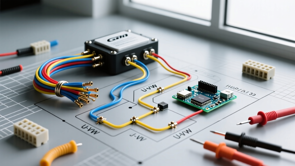
The core of the diagram will show three primary high-voltage lines connecting the motor controller (inverter) to the AC motor. These are universally labeled as U, V, and W.
- Phase U (Typically Yellow or Brown): Carries the first AC waveform from the inverter's first half-bridge.
- Phase V (Typically White or Black): Carries the second AC waveform, offset by 120 electrical degrees.
- Phase W (Typically Red or Grey): Carries the third AC waveform, offset by 240 electrical degrees.
Critical Note on Color Coding: While industrial 3-phase wiring follows strict NEC or IEC color codes, the EV automotive sector (governed by SAE J1673) mandates that all high-voltage cables feature an orange outer jacket. Therefore, in EV applications, U, V, and W cables will all be orange on the outside. You must rely on heat-shrink tubing labels (U, V, W) or phase-marking tape at the termination points to identify them. Swapping any two phases (e.g., U and V) will reverse the motor's direction of rotation. While this is easily fixed in software for some modern controllers, in older or simpler V/Hz drives, it can cause severe mechanical stress during initial testing.
2. The Resolver and Encoder Feedback Loop
A 3-phase AC motor cannot operate blindly; the inverter must know the exact angular position of the rotor to time the PWM (Pulse Width Modulation) switching. The wiring diagram will feature a 6-pin to 8-pin shielded low-voltage harness connecting the motor's internal resolver to the inverter.
- Excitation (R1, R2): The inverter sends a high-frequency AC reference signal (usually 4kHz to 10kHz) to the rotor winding.
- Sine (S1, S3) & Cosine (S2, S4): The stator windings return modulated signals based on the rotor's physical position.
- Shield/Drain Wire: Must be grounded to the connector backshell to prevent PWM noise from corrupting the resolver signal.
High-Voltage Cable Sizing and Shielding Matrix
Selecting the correct wire gauge is not just about ampacity; it is also about managing the 'skin effect' caused by high-frequency PWM switching. Standard copper THHN wire is unacceptable for EV 3-phase routing. You must use stranded, shielded EV-specific cable (such as LEONI or Huber+Suhner) with a cross-linked polyethylene (XLPE) insulation rated for 1000V+.
| Motor Model (Common EV) | Peak Phase Current | Nominal System Voltage | Recommended HV Cable Size | Estimated 2026 Cable Cost |
|---|---|---|---|---|
| NetGain Hyper9 | 300A (60 sec peak) | 144V DC | 2 AWG Shielded EV | $14 - $18 / ft |
| Cascadia iM-225 | 550A (10 sec peak) | 400V DC | 1/0 AWG Shielded EV | $22 - $28 / ft |
| BorgWarner HVH 250 | 450A (Continuous) | 350V DC | 1 AWG Shielded EV | $19 - $24 / ft |
Step-by-Step Inverter to Motor Wiring Procedure
Before touching any HV components, verify that the battery contactors are open, the manual service disconnect (MSD) is removed, and you are wearing Class 0 high-voltage safety gloves. As outlined by OSHA's electrical protective equipment standards, working on systems above 50V requires certified dielectric PPE and insulated tools.
- Verify Capacitive Discharge: Use a CAT III or CAT IV multimeter to measure DC voltage across the inverter's positive and negative DC bus bars. Wait until the reading drops below 30V before proceeding. This can take up to 15 minutes depending on the inverter's internal bleeder resistors.
- Prepare the Shielded Cable: Strip the orange outer jacket to expose the braided copper shield. Do not cut the shield. Fold the braid back and secure it using a 360-degree shield clamp or a dedicated shielded gland. The shield must be grounded at both the inverter and motor ends to contain EMI.
- Crimp and Terminate: Use a closed-barrel hex crimp for the inner conductor. Slide the heat shrink over the termination to seal the inner conductor from the shield.
- Torque to Specification: AC motor phase terminals (U, V, W) typically use M8 or M10 bolts with Belleville (conical spring) washers to maintain clamping force during thermal cycling.
- M8 Bolts: Torque to 20 - 25 Nm (15 - 18 lb-ft).
- M10 Bolts: Torque to 40 - 50 Nm (30 - 37 lb-ft).
- Connect the HVIL Loop: Modern 2026-compliant connectors (like Amphenol SurLok Plus) feature a High Voltage Interlock Loop (HVIL). Ensure the low-voltage HVIL pins are fully seated; otherwise, the inverter's safety logic will prevent the main contactors from closing.
WARNING: Never route the low-voltage resolver or CAN bus cables in the same conduit or bundle as the 3-phase high-voltage U, V, W cables. The massive dV/dt (voltage change over time) spikes generated by the inverter's IGBTs will induce high-frequency noise into the resolver lines, causing the motor controller to miscalculate rotor position and potentially trigger an overcurrent fault or violent torque shudder.
Edge Cases: Troubleshooting EMI and Phase Faults
Even with a perfect physical wiring diagram execution, EV builders frequently encounter edge cases during initial commissioning.
Fault Code: 'Phase Current Imbalance' or 'Overcurrent'
The Cause: This is rarely a bad motor. It is almost always caused by improper shield grounding on the 3-phase cables. If the braided shield is left 'floating' or pigtailed (wrapped into a single wire and screwed to a chassis point), it acts as an antenna rather than a Faraday cage. The resulting EMI floods the inverter's current Hall-effect sensors, causing the controller to read phantom current spikes and shut down.
The Fix: Ensure 360-degree shield terminations are used at both the motor junction box and the inverter output plate. Verify continuity between the cable shield and the metal chassis at both ends using a milliohm meter (target < 0.5 ohms).
Fault Code: 'Resolver Fault' or 'Position Sensor Error'
The Cause: The excitation or sine/cosine wires are swapped, or the shielding on the resolver cable is compromised. Another common issue is using unshielded twisted pair (UTP) wire for the resolver harness instead of shielded twisted pair (STP).
The Fix: Ohm out the resolver pins at the inverter connector against the motor's factory pinout sheet. Excitation (R1-R2) usually reads between 10 to 50 ohms, while Sine and Cosine windings typically read between 15 to 80 ohms. If the readings are open or shorted to the motor casing, the internal motor harness has been damaged during assembly.
Frequently Asked Questions
Can I use standard 3-phase industrial VFD cable for an EV?
While industrial VFD cable is shielded and rated for 600V-1000V, it lacks the extreme flexibility, fluid resistance, and abrasion resistance required for automotive environments. EV-specific cable (meeting SAE J1673 or ISO 6722-3) uses specialized XLPE insulation that can withstand engine bay heat, vibration, and exposure to oils and coolants. Always use automotive-grade HV cable.
Does the order of U, V, and W matter if I'm using a sensorless controller?
Yes. Even with sensorless field-oriented control (FOC), the inverter must auto-detect the motor's phase sequence and inductance during a 'commissioning spin.' If the physical wiring is highly asymmetric or if two phases are swapped, the auto-tuning routine will fail, or the motor will spin in reverse. Always wire U-to-U, V-to-V, and W-to-W as specified in the diagram, and use the controller's software to reverse direction if needed.
What is the purpose of the HVIL (High Voltage Interlock Loop)?
The HVIL is a low-voltage (usually 5V or 12V) safety circuit that runs through all high-voltage connectors in series. If a 3-phase cable is unplugged or vibrates loose while the system is energized, the HVIL circuit breaks. This instantly signals the inverter to open the main battery contactors and disable the IGBTs, preventing lethal arcing at the disconnected terminal.