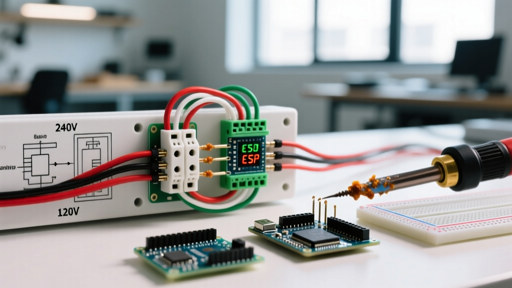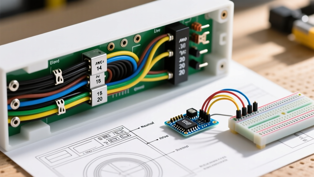

Decoding the Modern Washing Machine Electrical Wiring Diagram
Troubleshooting a modern washing machine goes far beyond checking for a tripped breaker. With the rise of inverter direct-drive motors, integrated steam heaters, and IoT-enabled smart control boards, the internal electrical architecture of a washer is highly complex. To accurately diagnose faults, you must be able to read a washing machine electrical wiring diagram and understand the critical distinctions between wire gauges (AWG) and internal appliance color codes.
Unlike residential branch circuit wiring governed strictly by the National Electrical Code (NEC), internal appliance wiring follows Underwriters Laboratories (UL) and international IEC standards. Misinterpreting these color codes or replacing a failed wire with an incorrect gauge or temperature rating is a leading cause of secondary component failure and fire hazards. This guide provides the exact reference data, gauge specifications, and troubleshooting frameworks required for safe, professional-grade appliance repair in 2026.
Branch Circuit vs. Internal Appliance Color Codes
The most common mistake DIYers make when reading a washing machine electrical wiring diagram is assuming internal wires follow standard NEC residential color codes (Black for Hot, White for Neutral, Green/Bare for Ground). Inside the appliance chassis, manufacturers utilize UL-rated Thermoplastic Equipment Wire (TEW) or cross-linked polyethylene (XLPE) wire, which adheres to entirely different color conventions.
Internal Appliance Wire Color Matrix
| Wire Color | Internal Function (North America / UL) | Internal Function (European / IEC) | Typical Schematic Label |
|---|---|---|---|
| Black | Line 1 (Hot) or Switched Hot | Line (Live) | L1, BK, BLK |
| White | Neutral (Sometimes) | Not typically used internally | N, WHT |
| Blue | Neutral or Low-Voltage DC | Neutral | N, BLU, BU |
| Red | Line 2 (Hot) or Motor Run | Switched Live / Control | L2, RD, RED |
| Brown | Heater Element or Motor Start | Line (Live) | HTR, BRN |
| Green / Yellow-Green | Chassis Ground | Protective Earth (PE) | GND, GRN |
| Orange / Yellow | Control Board Signals / Sensors | Control / Interlock | SIG, ORG, YEL |
Note: Always verify the specific legend printed on the physical schematic sheet tucked inside the washer's control panel or rear access panel, as manufacturers like Whirlpool, LG, and Samsung occasionally use proprietary color variations for sensor loops.
Wire Gauge (AWG) and Temperature Ratings by Component
Wire gauge selection in a washing machine is dictated by two factors: current draw (amperage) and ambient temperature near the wire routing. According to the National Fire Protection Association (NFPA) guidelines on appliance safety and UL 1015 standards for TEW wire, undersizing a wire or using a standard 60°C/75°C THHN wire near a tub heater will result in rapid insulation melting.
Washer Component AWG and Insulation Requirements
| Component | Typical Current Draw | Required Wire Gauge (AWG) | Min. Temp Rating & Insulation Type |
|---|---|---|---|
| Main Power Cord (120V) | 12A - 15A | 14 AWG (or 12 AWG) | 105°C SJT / SJTW (Stranded) |
| Internal Tub Heater | 10A - 13A (120V) | 12 AWG or 10 AWG | 150°C to 200°C Silicone / Fiberglass Braid |
| Drive Motor (Direct Drive) | 3A - 8A (Peak) | 16 AWG or 14 AWG | 105°C TEW (Stranded Copper) |
| Water Inlet Valves | 0.5A - 1A | 18 AWG | 105°C TEW or PVC |
| Control Board / Sensors | < 0.5A | 20 AWG or 18 AWG | 80°C to 105°C (Multi-conductor ribbon) |
| Drain Pump Motor | 1A - 2.5A | 16 AWG or 18 AWG | 105°C TEW |
Reading the Schematic: Line Thickness and Nomenclature
When examining a washing machine electrical wiring diagram, the visual weight of the lines provides immediate clues about the circuit's purpose:
- Heavy/Bold Lines: Represent high-current paths, such as the main L1/L2 feeds to the motor contactor, the heating element relay, or the main power entry. These correlate to 10-14 AWG wires.
- Thin/Light Lines: Represent low-current control circuits, sensor feedback loops (like the thermistor or tachometer), and DC voltage paths from the control board. These correlate to 18-22 AWG wires.
- Dashed Lines: Indicate mechanical linkages (e.g., the physical shaft connecting a timer motor to its cam switches) or shielded cable bundles (like the EMI-shielded harness connecting an inverter board to a direct-drive stator).
Real-World Troubleshooting: Motor and Heater Circuits
Modern washing machines frequently utilize brushless DC (BLDC) direct-drive motors and internal water heaters to meet the stringent energy and water efficiency standards tracked by the U.S. Department of Energy. These components place unique stresses on the wiring harness.
Common Failure Points and Edge Cases
- Heater Element Spade Connector Burnout: The internal tub heater draws roughly 12.5 amps at 120V. Over time, the vibration of the spin cycle causes the 0.250-inch (6.35mm) female spade connectors on the 12 AWG brown wires to loosen. This increases electrical resistance, generating intense localized heat that melts the TEW insulation. Fix: Never simply crimp a new standard vinyl-insulated spade. You must use a high-temperature silicone-insulated or fully metallic nickel-plated spade terminal, and apply a dielectric antioxidant paste to prevent future oxidation.
- Direct-Drive Stator Harness Chafing: The 3-phase wires (often colored U, V, W or Red, White, Blue) running from the inverter board to the stator at the rear of the tub are subject to extreme tub oscillation during agitation. If the 16 AWG wires rub against the plastic tub mold, the 105°C insulation wears through, causing a phase-to-phase short that instantly destroys the inverter board's IGBT transistors. Fix: Reroute the harness and wrap it in split-loom corrugated tubing secured with UV-resistant zip ties.
- Voltage Drop in Lid Switch Circuits: If a 20 AWG wire in the lid lock safety circuit develops a partial break inside the insulation (a 'greenstick' fracture), it may pass a continuity test with a multimeter but fail under load, causing the control board to throw an 'F5' or 'dE' (Door Error) code. Fix: Perform a voltage drop test across the harness while the circuit is actively energized rather than relying solely on passive continuity testing.
Sourcing UL-Rated Replacement Wire
When a section of the wiring harness is damaged beyond simple terminal replacement, you must source the correct replacement wire. Do not use standard automotive primary wire or residential THHN solid-core wire. Automotive wire is typically rated for only 60°C to 80°C and lacks the necessary voltage dielectric strength for 120V/240V appliance AC circuits. Solid-core THHN will snap from the vibration of the washer's spin cycle.
Always purchase UL 1015 rated TEW (Thermoplastic Equipment Wire) or UL 3135 rated Silicone wire. These are stranded (typically 16 to 26 strands depending on AWG), highly flexible, and rated for 600V AC. A 100-foot spool of 14 AWG UL 1015 TEW wire typically costs between $35 and $50 from industrial suppliers like Digi-Key or Mouser Electronics, which is more than enough for a lifetime of appliance repairs.
Frequently Asked Questions
Can I use a 14 AWG wire to replace a burnt 16 AWG wire on a drain pump?
Yes, you can always step up to a thicker wire gauge (lower AWG number) to handle more current and reduce voltage drop. However, the physical challenge is that a 14 AWG stranded wire may be too thick to properly crimp into the small 0.187-inch (4.75mm) spade terminals used on drain pump solenoids. If you must use 14 AWG, you will need to step down the wire size at the very end using a specialized crimp or by pigtailing a short 3-inch section of 16 AWG wire using a sealed heat-shrink butt connector.
Why does my washing machine schematic show a yellow/green wire connected to the tub?
This is the equipotential bonding ground. According to the Electrical Safety Foundation International (ESFI), large appliances with metal tubs and internal water heaters must have a dedicated bonding path to ensure that if a live wire faults to the metal chassis or water, the breaker trips instantly. Never remove or bypass this green/yellow bonding wire.
How do I identify the neutral wire on a 240V washer/dryer combo schematic?
For 240V compact combo units (common in European models or RV setups), the schematic will show L1 (Brown/Black), L2 (Red/Blue), and N (White/Blue). The neutral wire is strictly used to step down the voltage via a transformer on the main PCB to power the 120V control logic, water valves, and drain pump. It is usually a 14 AWG or 12 AWG white or light blue wire originating from the terminal block.