
The Anatomy of a 3-Way Lighting Circuit
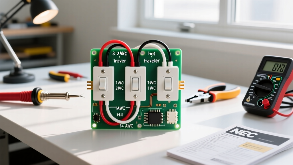
Before you pull a single foot of Romex, you must understand that a standard 3-way switch is electrically a Single-Pole, Double-Throw (SPDT) device. Unlike a standard single-pole switch that simply breaks or completes a single hot wire, a 3-way switch routes the incoming current down one of two possible 'traveler' paths. Mastering the wiring diagram for a 3 way switch requires shifting your mindset from simple on/off interruptions to managing continuous routing loops between two physical locations.
Whether you are wiring a new staircase in a 2026 custom build or retrofitting a mid-century hallway, the fundamental physics remain identical. However, modern National Electrical Code (NEC) requirements—specifically regarding neutral wire mandates at switch boxes—have drastically altered how we plan these circuits today compared to a decade ago.
Pre-Installation Planning: Power Source Scenarios
The most critical mistake DIYers make is assuming there is only one way to wire a 3-way circuit. In reality, the physical layout of your home dictates which of the two primary wiring diagrams you must follow. Identifying your power source location during the planning phase will determine your material list and wire routing strategy.
Scenario A: Power Source at Switch 1
This is the most straightforward configuration and the preferred method for new construction. The main power feed (14/2 or 12/2 NM-B) enters the first switch box. From Switch 1, a 3-conductor cable (14/3 or 12/3) runs to Switch 2, and another 2-conductor cable runs from Switch 2 up to the light fixture.
- Advantage: Switch 1 box houses the line, neutral, and ground, making it an ideal location for smart switches or GFCI/AFCI combo devices if required by local code.
- Wire Required: One run of 3-conductor cable between switches; one run of 2-conductor cable to the fixture.
Scenario B: Power Source at the Light Fixture
Common in retrofit projects and older homes, the power feed drops into the ceiling junction box first. To complete the circuit, you must drop a 2-conductor cable down to Switch 1, run a 3-conductor cable between Switch 1 and Switch 2, and use the white wire in the drop cable as a re-identified 'hot' feed (marked with black electrical tape or heat shrink) rather than a neutral.
- Disadvantage: Neither switch box contains a true neutral wire. Under NEC Article 404.2(A), switch boxes must have a neutral present to accommodate future smart switches or electronic timers. If you are pulling permits in 2026, this configuration will likely fail inspection unless you pull an additional neutral to at least one switch box.
NEC Box Fill Calculations & Wire Sizing
Cramming too many wires into a standard electrical box is a fire hazard and a direct violation of NEC Article 314.16. When planning your wiring diagram for a 3 way switch, you must calculate the cubic inch (cu in) volume required for each box. The 2023/2026 NEC updates have strictly enforced these fill capacities to prevent wire insulation damage and overheating.
| Wire Gauge | Volume per Wire (cu in) | Device Allowance (cu in) | Ground/Clamp Allowance | Recommended Box Size |
|---|---|---|---|---|
| 14 AWG (15A Circuit) | 2.0 cu in | 4.0 cu in (2x wire vol) | 2.0 cu in total | 18 cu in to 22 cu in (Deep Single Gang) |
| 12 AWG (20A Circuit) | 2.25 cu in | 4.5 cu in (2x wire vol) | 2.25 cu in total | 22.5 cu in to 25 cu in (Extra Deep Gang) |
Source Reference: For exact box fill formulas and device yoke calculations, consult the National Fire Protection Association (NFPA) NEC Handbook.
2026 Bill of Materials (BOM) & Pricing Guide
Material costs for copper wiring have fluctuated, but stabilizing supply chains in 2026 have brought residential electrical components to predictable price points. Below is a realistic BOM for a standard 15-Amp, 3-way hallway circuit spanning roughly 40 feet.
- Wire: Southwire SIMpull 14/3 NM-B (250 ft spool) - $115.00 - $130.00. (You only need about 50 ft, but spools are the standard retail unit. Alternatively, buy cut-to-length at big box stores for ~$0.75/ft).
- Switches: Leviton Decora 5603-2W (15A 3-Way, White) - $4.50 each. For a premium tactile feel, the Legrand radiant TM873WCCV4 runs about $9.00 each.
- Boxes: Carlon B618R-UPC 18 cu in. Non-Metallic Switch Box - $1.25 each.
- Connectors: Halex 3/8 in. 2-Screw NM Cable Connectors (10-pack) - $4.00.
- Wire Nuts: Ideal SureConnect Purple (12-10 AWG) or Yellow (14-12 AWG) - $8.00 per box.
Smart Switch Upgrades: The Neutral Wire Mandate
If your ultimate goal is to install smart lighting controls, your planning phase must account for the neutral wire. Standard mechanical 3-way switches do not require a neutral because they are passive routing devices. Smart switches, however, contain internal Wi-Fi, Zigbee, or Lutron Clear Connect radios that require constant standby power.
Pro-Tip for Smart Upgrades: If you are upgrading to a Lutron Caséta system, you only need one smart switch (e.g., PD-5S-DV) at the primary location, and a Pico Remote (PJ2-3BRL) mounted in a wallbox adapter at the secondary location. This completely eliminates the need to run 3-conductor traveler wires to the second box, saving hours of drywall fishing.
For deeper insights into modern switch requirements and smart home integrations, electrical professionals frequently reference the code breakdowns provided by Electrical Contractor Magazine (ECM).
Step-by-Step Execution & Pro Tips
- Kill and Verify: Turn off the breaker and use a non-contact voltage tester (like the Klein Tools NCVT-2) on the incoming wires. Test the tester on a known live circuit first to ensure the battery isn't dead.
- Strip and Prep: Strip 3/4 inch of insulation from the wire ends. Never strip more, as exposed copper outside the wire nut or terminal screw is a severe shock and arc-flash hazard.
- Identify the Common Terminal: On almost all modern 3-way switches (including Leviton and Eaton models), the 'Common' terminal is the dark-colored (usually black or dark brass) screw. The two 'Traveler' terminals are lighter brass. Never guess; look for the 'COM' stamp on the back of the switch yoke.
- Pigtail the Grounds: Instead of daisy-chaining the bare copper ground wires from device to device, use a yellow wire nut to pigtail all ground wires together with a 6-inch bare copper jumper that terminates on the green ground screw of the switch. This ensures the grounding path remains intact even if the switch is removed.
- Torque to Spec: While most residential switches don't have strict inch-pound torque requirements listed on the device, a firm hand-tighten followed by a 1/4 turn with a screwdriver is standard. Avoid over-torquing, which can strip the brass terminal threads.
Common Failure Modes & Troubleshooting Edge Cases
Even with a perfect wiring diagram for a 3 way switch, installation errors happen. If your circuit fails to operate correctly, check these specific edge cases:
The 'Toggle Dependent' Failure
Symptom: Switch A turns the light on and off perfectly. But if Switch B is flipped, Switch A stops working entirely.
Cause: The 'Line' (incoming hot) or 'Load' (outgoing to fixture) wire is incorrectly landed on a Traveler terminal instead of the Common terminal on one of the switches.
Fix: Identify the single wire that is独自 (alone) in its cable bundle at each switch and ensure it is connected to the dark Common screw.
The Phantom Voltage / LED Flicker
Symptom: Using LED bulbs, the light faintly glows or flickers when turned off.
Cause: Capacitive coupling between the parallel traveler wires in the 14/3 cable, combined with the low power draw of LED drivers.
Fix: Install an Lutron LUT-MLC (Minimum Load Capacitor) across the load wires at the light fixture, or upgrade to higher-quality LED bulbs with built-in PWM drivers that resist phantom voltage.
Final Inspection Readiness
Before calling for your rough-in or final inspection, ensure all wires are neatly folded into the back of the box using the 'Z-fold' method. Push the grounds to the very back, followed by the neutrals, and finally the hots and device yoke. A clean, well-organized box signals to the inspector that the installer respects the craft and the fundamental safety practices of residential wiring. Proper planning using the correct wiring diagram for a 3 way switch guarantees a safe, code-compliant, and frustration-free installation.