
Decoding the Wiring Diagram for Air Conditioner Thermostat Systems
Upgrading your HVAC system's control interface requires a precise understanding of low-voltage circuits. In 2026, with the U.S. Department of Energy's updated efficiency mandates pushing more homeowners toward intelligent climate control, understanding the wiring diagram for air conditioner thermostat configurations is more critical than ever. Whether you are installing a premium smart device like the Ecobee SmartThermostat Premium ($249) or a reliable workhorse like the Honeywell Home T9 ($179), the foundational 24V AC control logic remains consistent across conventional split systems.
This guide provides a comprehensive, step-by-step walkthrough for wiring a standard central air conditioning system. We will cover terminal mappings, C-wire solutions, and air handler control board verifications to ensure your installation is both safe and fully functional.
Conventional 24V vs. Proprietary Communicating Systems
Before touching any wires, you must identify your system type. The wiring diagram for air conditioner thermostat setups generally falls into two categories:
- Conventional 24V AC Systems: These use standard 18 AWG multi-conductor wire (typically 18/5 or 18/8) to send binary on/off signals via 24-volt alternating current. This is the most common setup in residential homes and is compatible with 95% of aftermarket thermostats.
- Communicating Systems: High-end systems (like Carrier Infinity or Trane ComfortLink) use a proprietary RS-485 data bus. These require specific communicating thermostats and use A/B or data terminals rather than standard R/Y/G/W/C terminals. Do not wire a standard 24V thermostat to a communicating control board; you will instantly fry the thermostat's logic board.
Essential Tools and Safety Protocols
CRITICAL SAFETY WARNING: While thermostat wire carries a relatively safe 24V AC, the air handler and condenser units contain lethal 120V/240V line voltage. Always kill power at the main breaker panel before opening the air handler control board.
To execute this wiring walkthrough professionally, gather the following tools:
- Digital Multimeter: A True-RMS meter like the Fluke 117 is essential for verifying 24V AC and checking for zero line voltage.
- Wire Strippers: Klein Tools 11055 or similar precision strippers for 18-22 AWG solid copper wire.
- Thermostat Wire: 18/5 or 18/8 solid copper Class 2 thermostat wire (UL listed) if you need to run a new C-wire.
- Non-Contact Voltage Tester: For a secondary safety check on high-voltage components near the control board.
Standard 24V AC Terminal Mapping Matrix
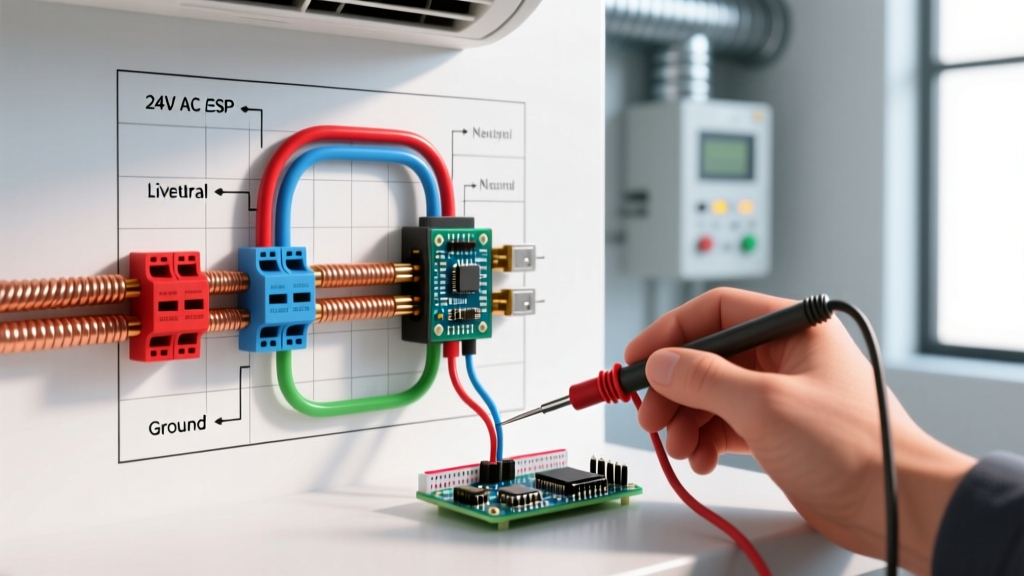
The core of any wiring diagram for air conditioner thermostat installs relies on standard terminal designations. Below is the definitive mapping matrix for conventional central AC and heat pump systems.
| Terminal | Standard Wire Color | Function & Voltage State | System Component Controlled |
|---|---|---|---|
| Rc / Rh | Red | 24V AC Hot (Power Source) | Main transformer secondary |
| Y / Y1 | Yellow | 24V AC Signal (Cooling Call) | Outdoor condenser compressor contactor |
| Y2 | Light Blue / White | 24V AC Signal (2nd Stage Cool) | Two-stage compressor second stage |
| G | Green | 24V AC Signal (Fan Call) | Indoor air handler blower relay |
| W / W1 | White | 24V AC Signal (Heating Call) | Furnace gas valve or heat strip relay |
| C | Blue / Black | 24V AC Common (Return Path) | Continuous power for smart thermostats |
| O/B | Orange / Dark Blue | Reversing Valve Signal | Heat pump changeover valve (O=Cool, B=Heat) |
Step-by-Step Thermostat Wiring Walkthrough
Step 1: Kill Power and Verify Zero Voltage
Navigate to your main electrical panel and switch off the breakers labeled 'Air Handler' (or Furnace) and 'AC Condenser'. At the thermostat, attempt to turn on the fan and AC to confirm the system is dead. Next, open the air handler access panel and use your Fluke 117 multimeter to test across the L1 and L2 line voltage terminals on the control board to guarantee 0V.
Step 2: Audit and Label Existing Control Wires
Remove the faceplate of your old thermostat. Before disconnecting a single wire, use the included adhesive stickers to label every wire according to the terminal it is currently occupying. Pro Tip: Ignore the physical color of the wire; previous installers often use whatever color was left in the spool. Always wire based on the terminal designation (e.g., if a black wire is in the 'Y' terminal, it is your compressor signal, regardless of color).
Step 3: Address the C-Wire (Common) Deficit
Modern smart thermostats require continuous 24V AC power to run Wi-Fi radios and backlit displays. If your wall only has 4 wires (R, W, Y, G) and no C-wire, you have two options:
- Pull New Wire: Run a new 18/5 or 18/8 cable from the air handler to the wall. This is the most reliable, code-compliant method.
- Use a Power Extender Kit (PEK): Devices like the Ecobee PEK or Fast-Stat 5A use a multiplexer at the control board to send power and signals over existing wires. While convenient, PEKs can occasionally cause contactor chatter on older HVAC systems.
Step 4: Terminate the Thermostat Baseplate
Thread the 18 AWG wires through the new mounting plate. Use your precision strippers to remove exactly 1/4 inch of insulation. Insert the wires into the corresponding terminal blocks: Red to Rc, Yellow to Y, Green to G, White to W, and Blue to C. Tighten the set screws firmly and give each wire a gentle tug to ensure a solid mechanical connection. A loose C-wire connection is the #1 cause of smart thermostat reboots.
Step 5: Verify Air Handler Control Board Terminations
Many DIY guides stop at the wall, but a proper wiring diagram for air conditioner thermostat installation requires verifying the other end of the circuit. At the air handler control board, ensure the Red wire lands on the 'R' or 'V' terminal, the Yellow wire on 'Y', and crucially, the Blue C-wire on the 'C' terminal. Never wire the C-wire to the ground chassis or a neutral bus bar; it must return to the 24V transformer's common secondary post.
Real-World Troubleshooting: Edge Cases and Failure Modes
Even with a perfect diagram, field conditions can introduce errors. Refer to this troubleshooting matrix if your system behaves erratically post-installation.
| Symptom | Probable Wiring Error | Corrective Action |
|---|---|---|
| Indoor fan runs, but no cold air from vents. | Y (Compressor) and G (Fan) wires are swapped. | Swap Yellow and Green wires at both thermostat and control board. |
| Thermostat screen turns on, but dies when AC kicks in. | Missing or loose C-wire causing 'power stealing' dropout. | Verify C-wire continuity from thermostat to transformer common. |
| Heat pump blows cold air in heating mode. | O/B reversing valve configuration is inverted. | Change O/B setting in thermostat menu (Carrier=B, Rheem/Trane=O). |
| Outdoor condenser clicks rapidly but won't start. | 18 AWG wire run exceeds 100 feet, causing voltage drop below 18V. | Upgrade to 16 AWG wire or install a hardstart kit on the compressor. |
Frequently Asked Questions
Can I use a ground wire as a C-wire?
No. According to the NFPA 70 (National Electrical Code), equipment grounding conductors shall not be used as current-carrying neutral or common conductors. Doing so can introduce 60Hz hum into your control circuits and create a shock hazard if the ground loop is broken.
Do I need a C-wire for a basic programmable thermostat?
Basic battery-operated programmable thermostats do not require a C-wire. However, as noted by the ENERGY STAR program, smart thermostats that qualify for utility rebates and offer advanced learning algorithms universally require a continuous 24V AC common connection to maintain Wi-Fi connectivity.
What is the difference between Rc and Rh?
In systems with a single transformer (most standard split systems), Rc and Rh are internally jumpered, and you can use either. In dual-transformer systems (e.g., a separate boiler for heat and an AC unit for cooling), Rh connects to the heating transformer's hot leg, and Rc connects to the cooling transformer's hot leg. The thermostat must be configured to isolate them, or you will cross-feed 24V back into the wrong transformer, potentially blowing its low-voltage fuse.
Final Thoughts on HVAC Control Wiring
Mastering the wiring diagram for air conditioner thermostat configurations empowers you to upgrade your home's comfort system safely and efficiently. By strictly adhering to terminal designations rather than wire colors, verifying the C-wire return path, and understanding the distinction between conventional and communicating systems, you ensure optimal performance and longevity for your HVAC equipment. For more information on maximizing your system's seasonal energy efficiency ratio (SEER), consult the U.S. Department of Energy's thermostat guidelines.