
Introduction to Circuit Breaker Wiring & NEC Compliance
Understanding a wiring diagram for circuit breaker panels is the foundational step in ensuring residential and commercial electrical safety. As electrical loads increase with the adoption of EV chargers, heat pumps, and smart home systems, the modern electrical panel is under more stress than ever. In 2026, adherence to the latest National Electrical Code (NEC) cycles is not just a legal requirement—it is a critical defense against arc flashes, thermal fires, and equipment failure.
According to the National Fire Protection Association (NFPA), electrical failures or malfunctions are a leading cause of home fires. A properly executed wiring diagram ensures that overcurrent protection devices operate exactly as engineered, clearing faults in milliseconds. This guide breaks down the anatomy, code requirements, and step-by-step wiring procedures for single-pole, double-pole, and advanced AFCI/GFCI breakers.
Anatomy of a Standard Panel Wiring Diagram
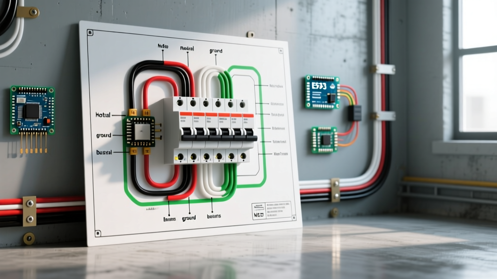
Before pulling wire, you must understand the physical layout of a standard 120/240V split-phase load center (such as a Square D QO or Eaton BR series). A standard wiring diagram for a circuit breaker panel revolves around four primary conductive pathways:
- Hot Bus Bars (A and B Phases): Two alternating copper or aluminum bars running down the center of the panel. Each provides 120V relative to ground, and 240V across both phases.
- Neutral Bus Bar: The silver-colored bar where all grounded (white) conductors terminate. In a main service panel, this is bonded to the ground.
- Ground Bus Bar: The green or bare copper termination point for equipment grounding conductors. In subpanels, this must remain strictly isolated from the neutral bar.
- Main Lugs / Main Breaker: The entry point for the service drop, typically rated for 200A to 400A in modern residential builds.
The Critical Role of the Wiring Schematic
Every panel manufacturer provides a specific wiring schematic on the inside of the panel door. This diagram dictates the allowable breaker types (e.g., CTL vs. non-CTL), the maximum bus bar rating, and the specific torque requirements for the lugs. Ignoring this diagram and mixing breaker brands (like installing a Siemens breaker in a Challenger panel) violates NEC 110.3(B) and creates severe fire hazards due to mismatched bus bar stab geometries.
Step-by-Step Wiring Diagram for 120V & 240V Breakers
Below is the actionable execution of standard wiring diagrams for the most common circuit configurations.
1. 120V Single-Pole Breaker Wiring (15A & 20A)
Used for standard lighting and receptacle circuits. The wiring diagram flows as follows:
- Ground First: Terminate the bare copper or green wire to the ground bus bar. Torque to manufacturer specs (typically 35 in-lbs for 14-10 AWG).
- Neutral Connection: Terminate the white insulated wire to the neutral bus bar. Code Alert: NEC 408.41 strictly prohibits mixing neutrals and grounds on the same lug unless specifically listed for it.
- Hot Connection: Route the black insulated wire to the single-pole breaker terminal. Ensure the wire insulation is stripped exactly to the indicator mark on the breaker (usually 1/2 inch to 5/8 inch). No exposed copper should be visible outside the lug, and no insulation should be trapped under the screw.
- Seating: Snap the breaker onto the hot bus bar stab, ensuring a firm, flush fit.
2. 240V Double-Pole Breaker Wiring (30A & 50A)
Used for heavy appliances like water heaters, HVAC compressors, and Level 2 EV chargers. A 240V wiring diagram requires connecting to both the A and B phase bus bars simultaneously.
- Pure 240V (e.g., Baseboard Heater): Requires two hot wires (typically Black and Red) connected to the two poles of the double-pole breaker. The ground wire goes to the ground bar. No neutral is required.
- 120/240V (e.g., Electric Dryer or Range): Requires two hots (Black and Red) to the breaker, a ground to the ground bar, AND a white neutral wire to the neutral bar to power the 120V control boards and timers inside the appliance.
3. AFCI and GFCI Breaker Wiring Diagrams
Modern code cycles mandate Arc Fault (AFCI) and Ground Fault (GFCI) protection for nearly all living spaces and wet areas. The wiring diagram for these breakers includes a crucial extra step: the coiled white pigtail.
Expert Insight: The white pigtail on an AFCI/GFCI breaker is NOT the circuit neutral. It is the power supply for the breaker's internal microprocessor. You must connect this pigtail directly to the panel's neutral bus bar. The circuit's actual white neutral wire must be connected to the screw terminal on the breaker itself, marked 'Load Neutral'. Reversing these will cause the breaker to trip immediately or fail to provide protection.
NEC Code Compliance & Torque Matrix (2026 Standards)
One of the most heavily cited violations by electrical inspectors is improper termination torque. Under NEC Article 110.14(D), all electrical connections must be tightened to the manufacturer's specified torque using a calibrated tool. Hand-tightening with a standard screwdriver is a guaranteed path to thermal failure due to thermal cycling and wire creep.
| Breaker Amperage | Wire Gauge (Copper) | Strip Length | Target Torque (in-lbs) | Tool Recommendation |
|---|---|---|---|---|
| 15A - 20A | 14 - 10 AWG | 1/2" - 5/8" | 35 in-lbs | Klein Tools 69406 |
| 30A - 40A | 10 - 8 AWG | 5/8" - 3/4" | 40 in-lbs | Wiha 61100 |
| 50A - 60A | 6 - 4 AWG | 3/4" - 7/8" | 45 - 50 in-lbs | CDI Torque Screwdriver |
| 100A (Main) | 2 - 1/0 AWG | 1" - 1 1/8" | 180 - 250 in-lbs | Calibrated Torque Wrench |
Note: Always verify torque values against the specific label inside your panel door, as manufacturer specifications supersede general guidelines.
Common Wiring Diagram Mistakes & Failure Modes
Even experienced DIYers make critical errors when interpreting or executing a wiring diagram for circuit breaker installations. Avoid these catastrophic failure modes:
1. Double-Tapping Hot Lugs
Connecting two hot wires under a single breaker screw is a direct violation of NEC 110.14(A) unless the lug is explicitly listed for two conductors (which is exceedingly rare for breaker hot terminals). The Fix: Use a wire nut to pigtail the two wires into a single conductor, or install an accessory lug on the bus bar if space permits.
2. The 'Floating' Neutral in Subpanels
When wiring a subpanel (e.g., for a detached garage), the wiring diagram changes drastically. The neutral and ground bars must be physically separated. The green bonding screw or strap must be removed. If a ground fault occurs in a bonded subpanel, return current will travel back via the equipment grounding wire, potentially energizing the exterior of appliances and creating a lethal shock hazard.
3. Aluminum Wire Oxidation
If your wiring diagram involves older aluminum branch wiring (common in the 1970s) or modern aluminum service entrance cables, you must apply an antioxidant compound (like Noalox) to the stripped wire before termination. Aluminum oxidizes rapidly, creating a high-resistance layer that generates intense heat, leading to melted breaker housings and fires.
Safety Protocols & Arc Flash Mitigation
Working inside a live panel exposes you to lethal voltages and arc flash risks. The Occupational Safety and Health Administration (OSHA) mandates strict protocols for electrical work. Always use a non-contact voltage tester and a multimeter to verify the absence of voltage on the bus bars before touching any terminals. Wear appropriate PPE, including arc-rated clothing and insulated gloves, when measuring live circuits. If you are unsure about your panel's condition, particularly in homes with known hazardous panels like Federal Pacific Electric (FPE) or Zinsco, hire a licensed electrician immediately, as these panels are known to fail to trip during short circuits.
Frequently Asked Questions (FAQ)
Can I use a 20A breaker with 14 AWG wire?
No. The wiring diagram and NEC Article 240.4(D) strictly limit 14 AWG copper wire to a maximum 15A breaker. Using a 20A breaker allows the wire to overheat and melt its insulation before the breaker ever trips, creating a severe fire hazard inside your walls.
Why does my AFCI breaker trip when I plug in a vacuum?
Older universal motors in vacuums and power tools generate heavy electrical noise and minor arcing at the brushes. Early-generation AFCI breakers misinterpreted this as a dangerous arc fault. Modern 2026-era combination AFCI breakers feature advanced digital signal processing to filter out normal appliance 'noise' while still detecting hazardous parallel and series arcs. For more on AFCI technology, refer to the Consumer Product Safety Commission (CPSC) guidelines.
Do I need to torque the neutral and ground bars too?
Yes. NEC 110.14(D) applies to all terminations, including the neutral and ground bus bars. A loose neutral connection is actually more dangerous than a loose hot connection, as it can cause severe voltage imbalances in a multi-wire branch circuit (MWBC), sending 240V into 120V appliances and destroying their electronics.