
Introduction to 24V AC Control Circuits
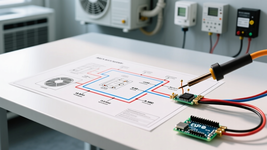
When installing or troubleshooting residential and light-commercial HVAC systems, understanding the low voltage wiring diagram for air conditioner control circuits is mandatory. While the line voltage (120V to 240V) powers the heavy loads like the compressor and blower motor, the low voltage side (typically 24V AC) acts as the nervous system. It dictates when the system turns on, modulates, and shuts down. In 2026, with the widespread adoption of high-efficiency variable-speed systems and smart thermostats, the low voltage circuit has evolved from a simple switch loop into a complex data network.
Misinterpreting these diagrams or using improper wire gauges can lead to blown control board fuses, contactor chatter, or catastrophic failure of expensive inverter boards. This appliance wiring tutorial breaks down the exact specifications, wiring topologies, and failure modes associated with modern 24V AC control circuits.
Conventional vs. Communicating Low Voltage Wiring Diagrams
Before pulling any wire, you must identify whether your system uses a conventional parallel circuit or a serial communicating bus. The wiring diagrams for these two architectures are fundamentally incompatible.
Standard 5-Wire Conventional Setup (R, W, Y, G, C)
In a conventional system, the air handler control board (e.g., Honeywell ST9120U or Goodman B1859014S) uses a 40VA step-down transformer to provide 24V AC. The wiring diagram relies on discrete, dedicated circuits for each function:
- R (Red): 24V AC Hot from the transformer secondary.
- C (Blue/Black): 24V AC Common (the return path for all control circuits).
- Y (Yellow): Compressor contactor coil. When the thermostat closes the R-Y circuit, 24V energizes the outdoor contactor.
- G (Green): Indoor blower fan relay.
- W (White): Heating sequence (gas valve, heat strips, or reversing valve for heat pumps).
Expert Insight: If you are installing a Wi-Fi smart thermostat (like an Ecobee or Nest) on a conventional system, the C-wire is non-negotiable. Attempting to "power steal" through the Y or W circuit without a C-wire can cause phantom voltage to energize the outdoor contactor, leading to short-cycling and compressor damage.
Modern Communicating Systems (Carrier Infinity, Trane ComfortLink)
Modern variable-capacity systems do not use discrete 24V AC switching. Instead, they use a digital data bus superimposed over a DC or AC carrier wave. For example, Carrier Infinity systems use a 4-wire (A, B, C, D) serial bus. Trane ComfortLink uses a 4-wire (B, D, O, T) setup.
When reading the low voltage wiring diagram for air conditioner communicating setups, you will notice that terminals are polarity-sensitive or require specific data-pair routing. Standard thermostat wire can work, but shielded 18 AWG cable is highly recommended to prevent electromagnetic interference (EMI) from nearby line-voltage cables, which can corrupt the serial data packets and throw "Loss of Communication" fault codes.
Wire Gauge Selection and Routing Specifications
Voltage drop is the silent killer of low voltage HVAC circuits. A standard 24V AC transformer outputs roughly 26V to 28V under no load. If the wire run is too long or the gauge is too thin, the voltage at the outdoor contactor coil may drop below 18V. This prevents the magnetic field from fully pulling in the contactor, resulting in a loud 60Hz buzz, arcing across the high-voltage contacts, and eventual coil burnout.
| Wire Gauge (Solid Copper) | Max Recommended Distance | Typical Application | Voltage Drop at Max Load (2A) |
|---|---|---|---|
| 20 AWG | Under 50 feet | Short retrofits, basic non-Wi-Fi thermostats | ~2.1V |
| 18 AWG | Up to 100 feet | Standard new construction, smart thermostats | ~1.3V |
| 16 AWG | Up to 150 feet | Long runs to distant condenser pads, humidifiers | ~0.8V |
| 14 AWG | Up to 250 feet | Light commercial, rooftop units (RTUs) | ~0.5V |
Pro Tip: Always use 18 AWG solid copper thermostat wire (e.g., Southwire 5-conductor) for residential runs. Avoid Copper-Clad Aluminum (CCA) wire, which has higher resistance and is prone to snapping under terminal screw pressure.
Step-by-Step Appliance Wiring Tutorial: Connecting the Control Board
Follow these precise steps when terminating low voltage wires at the air handler control board and thermostat baseplate to ensure compliance with the ACCA Quality Installation (QI) standards.
- Power Down: Turn off both the 120V/240V line voltage disconnect and the indoor air handler service switch. Verify zero voltage with a multimeter.
- Strip the Jacket: Remove exactly 2 inches of the outer PVC jacket from the thermostat cable. Do not nick the inner conductors.
- Strip the Conductors: Strip 5/16 inch of insulation from the individual 18 AWG wires. Stripping them too short prevents full insertion; stripping them too long exposes bare copper, creating a short-circuit hazard.
- Form the Shepherd's Hook: Bend the bare wire into a tight "U" shape (shepherd's hook) using needle-nose pliers. This ensures maximum surface area contact under the terminal screw.
- Terminate and Torque: Insert the hook under the terminal screw so that tightening the screw pulls the wire in, rather than pushing it out. Tighten to approximately 12 in-lbs. Give each wire a firm tug to verify mechanical retention.
- Dress the Wires: Route the low voltage wires away from the 120V/240V blower motor leads. The National Electrical Code (NEC) Article 725 mandates that Class 2 (low voltage) circuits be separated from Class 1 (line voltage) circuits by at least 2 inches or a physical barrier to prevent inductive interference and shock hazards.
Troubleshooting Common Low-Voltage Failure Modes
When an air conditioner fails to respond to a thermostat call for cooling, the issue is frequently isolated to the low voltage circuit. Here is how to diagnose the most common edge cases.
The Blown 3-Amp Control Board Fuse
Almost all modern control boards feature a 3-amp automotive-style blade fuse (usually purple) on the 24V hot leg leaving the transformer. If this fuse blows, the entire system dies.
Diagnostic Rule: Never simply replace a blown 3A fuse and reset the system. A blown fuse indicates a direct short to ground. If you replace it without finding the short, the new fuse will blow instantly, and you risk destroying the control board's PCB traces.
Common Shorts: A chewed thermostat wire in the attic, a bare Y-wire touching the copper refrigerant line outside, or a failed outdoor contactor coil. To test the contactor coil, disconnect the Y and C wires at the condenser and measure resistance across the coil terminals with a multimeter. A healthy 24V coil should read between 10 and 20 ohms. If it reads less than 5 ohms, the coil is internally shorted and must be replaced (e.g., Mars 208/240V 40VA contactor replacement).
Transformer Overload and Contactor Chatter
Standard 40VA transformers are sufficient for basic systems. However, if you add a 15VA UV air purifier, a 10VA electronic air cleaner, and a smart thermostat, you may exceed the transformer's capacity. According to Department of Energy HVAC installation guidelines, undersized control power supplies lead to severe voltage sag during the high inrush current required to pull in the outdoor contactor.
The Fix: Upgrade the control transformer from 40VA to a 75VA model (such as the Honeywell AT72D1683). This provides ample overhead for inrush currents and auxiliary accessories, eliminating voltage drop and contactor chatter.
Final Code Compliance and Safety Checks
Before closing up the air handler panel and applying power, perform a final continuity check. Set your multimeter to the continuity/beep setting. Place one probe on the R terminal and the other on the C terminal at the thermostat baseplate. It should read "OL" (Open Loop). If it beeps, you have a dead short between R and C, and applying power will instantly blow the board fuse. Once verified open, restore power, check for 24V-28V AC across R and C at the thermostat, and initiate a cooling call to verify proper contactor engagement.