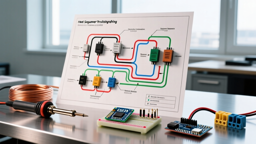

The Critical Role of Heat Sequencers in Electric Furnaces
Electric furnaces and high-capacity air handlers rely on heat sequencers to stage 240V electric resistance heating elements. If all elements engaged simultaneously, the massive current inrush would instantly trip the main circuit breaker or cause severe voltage sags across the home's electrical panel. A heat sequencer uses a 24V control signal to activate internal bimetallic switches and tiny heater coils, closing high-voltage contacts in a timed sequence—typically spacing stages 15 to 45 seconds apart.
When an electric furnace fails to produce heat, blows cold air, or runs continuously without shutting off, the sequencer is often the culprit. However, blindly replacing parts is a costly mistake. By learning how to read a wiring diagram for heat sequencer circuits, HVAC technicians and advanced DIYers can isolate the exact point of failure, whether it is a burnt-out 24V coil, a welded high-voltage contact, or a faulty blower interlock.
Safety Warning: Electric furnaces operate on lethal 240V line voltage. Always adhere to OSHA's Lockout/Tagout (LOTO) standards by shutting off the main disconnect and verifying zero energy with a CAT III or CAT IV multimeter before opening the air handler cabinet.
Anatomy of a Heat Sequencer Wiring Diagram
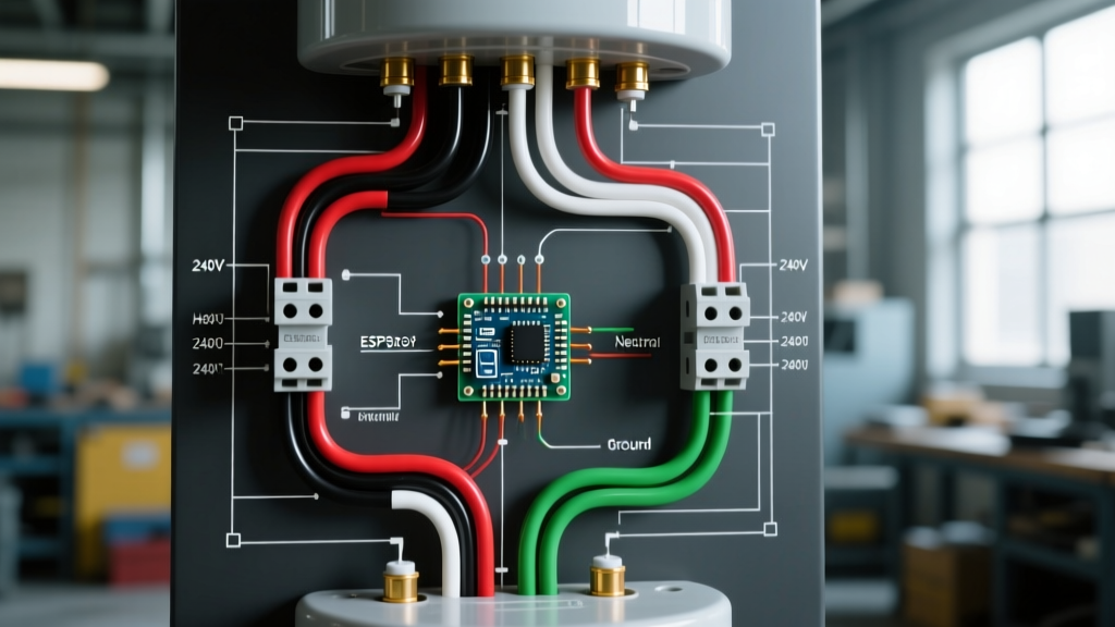
Before grabbing a multimeter, you must understand the schematic symbols and terminal designations commonly found on the air handler's wiring diagram. While specific models like the White-Rodgers 50M56U-843 or universal replacements like the Supco SQ100 vary slightly in physical layout, their electrical logic remains identical.
Standard Terminal Designations
- H1, H2, H3 (Heater Coils): These connect to the 24V control circuit. When the thermostat calls for heat, 24V AC is applied here, energizing the internal timing heater.
- C (Common): The 24V return path for the sequencer coils.
- L1, L2 (Line Voltage In): 240V AC input from the main circuit breaker or fuses.
- E1, E2 (Element Out): 240V AC output to the nichrome wire heating elements once the internal bimetallic contacts close.
- M / B (Motor / Blower): A dedicated set of contacts or a parallel wiring node used to trigger the blower motor relay or directly power the blower's low-speed heating tap.
4-Step Diagnostic Flow Using the Schematic
Troubleshooting with a wiring diagram requires a systematic approach, moving from the low-voltage control side to the high-voltage load side. According to the U.S. Department of Energy, electric resistance heating is nearly 100% efficient at the point of use, meaning any lack of heat output is strictly a delivery or control failure, not a thermodynamic one.
Step 1: Verify the 24V Control Signal
Set your multimeter to AC Voltage. With the thermostat calling for heat, place your probes on the sequencer's H terminal and the C (Common) terminal. You should read between 24V and 28V AC. If you read 0V, the issue is upstream: check the thermostat's W terminal, the limit switches, and the control board relay. The sequencer cannot be blamed if it never receives the signal.
Step 2: Test Sequencer Coil Continuity (Power OFF)
If 24V is present but the sequencer doesn't click after 15–30 seconds, the internal bimetallic heater coil may be open. Turn off the LOTO disconnect. Set your meter to Ohms (Ω). Disconnect the wires from H and C, and measure across the sequencer's coil terminals. A healthy 24V sequencer coil typically reads between 10 and 30 ohms. An infinite reading (OL) confirms a burnt-out internal coil, requiring a full sequencer replacement (OEM parts typically cost $45–$75, while universal models like the Supco SQ100 run about $35).
Step 3: Verify Line Voltage Staging and Timing
Restore power and initiate a heat call. Monitor the E (Element) terminals relative to L1.
Stage 1: Should show 240V AC within 10 to 15 seconds.
Stage 2: Should show 240V AC within 30 to 45 seconds.
If Stage 1 closes but Stage 2 never closes despite 24V being present at H2, the second sequencer stack has failed mechanically or electrically.
Step 4: The Blower Interlock Check
The wiring diagram for heat sequencer circuits usually routes the blower motor's low-speed wire through a set of normally-open (NO) contacts on the first sequencer stack. If the heating elements are glowing red but the blower is dead, check for 240V (or 120V, depending on the motor design) across the blower interlock terminals on the sequencer. If voltage enters the sequencer's M terminal but does not exit to the motor, the internal blower contacts are pitted or broken.
Troubleshooting Matrix: Symptoms vs. Schematic Checkpoints
| System Symptom | Diagram Node to Check | Expected Reading | Probable Failure Mode |
|---|---|---|---|
| Furnace blows cold air; elements never energize. | H1 to C (24V Control) | 24V - 28V AC | Open limit switch, faulty thermostat, or broken 24V transformer. |
| Elements stay ON continuously; won't shut off. | L1 to E1 (Line Voltage) | 0V when thermostat is satisfied | Welded Contacts: High inrush current fused the sequencer's internal bimetallic switch shut. Immediate replacement required. |
| Breaker trips instantly upon heat call. | E1 to Heating Element | 10 - 25 Ohms (Element Resistance) | Shorted heating element or grounded nichrome wire, NOT the sequencer itself. |
| Heat works, but blower motor never turns on. | M (Motor Interlock) In/Out | 120V/240V AC across closed contacts | Pitted blower contacts inside sequencer or failed blower motor capacitor. |
Advanced Edge Cases: When the Diagram 'Lies'
Experienced technicians know that a wiring diagram represents a perfect electrical state. In the real world, physical degradation creates edge cases that mimic other failures.
1. Voltage Drop Across Pitted Contacts
Over years of switching 240V and 20+ amps, the internal contacts of a heat sequencer can become carbon-scored and pitted. A standard multimeter might show 240V passing through the closed contact, but under load, the resistance causes a severe voltage drop. The heating element might only receive 190V, drastically reducing its BTU output (since power equals voltage squared divided by resistance). Pro Tip: Measure voltage directly across the element terminals while the system is running. If you read 210V or less at the element while the panel supplies 240V, the sequencer contacts are degraded.
2. The 'Runaway' Furnace (Welded Contacts)
If a heating element shorts out or ages, its resistance can drop, causing a massive spike in amperage when the sequencer attempts to close the circuit. This arc-welds the bimetallic contacts together. Even when the thermostat drops the 24V call for heat, the 240V line continues to feed the element. This is a severe fire hazard. Wire sizing and overcurrent protection must strictly comply with NFPA 70 (National Electrical Code) Article 424 to ensure the branch circuit breaker trips before the wiring inside the walls melts.
3. Blower Delay Timing Issues
Some older schematics utilize a separate 'blower delay' sequencer (often a single-pole, single-throw device) wired in parallel with the first heat stage. If the blower turns on before the heat strips energize, blowing cold air on the occupant, check the wiring diagram to ensure the delay sequencer hasn't been bypassed or wired out of sequence by a previous, less-qualified repair technician.
Summary: Trust the Schematic, Verify with Data
A wiring diagram for heat sequencer systems is your roadmap, but your multimeter provides the ground truth. By methodically tracing the 24V control logic, verifying coil continuity, and measuring high-voltage load delivery under operating conditions, you can confidently diagnose electric furnace failures. Always prioritize safety, respect the 240V line, and replace failed sequencers with OEM or high-quality universal equivalents rated for your specific kW element load.