
Applying Automotive Harness Diagnostics to the Kenmore 110 Series
When technicians approach the wiring diagram for Kenmore dryer model 110 (a heavy-duty appliance series predominantly manufactured by Whirlpool for Sears), they typically rely on basic appliance repair methodologies. However, treating the dryer’s 240V/120V split electrical system with the rigor of a Vehicle-Specific Guide—the exact framework used by master automotive technicians to diagnose complex chassis harnesses and ECU networks—yields vastly superior troubleshooting results. In 2026, with replacement drive motors costing between $145 and $180 and smart control boards exceeding $220, misdiagnosing a simple harness fault is an expensive mistake.
By mapping the Kenmore 110’s schematic to automotive logic, we can isolate parasitic draws, perform live voltage-drop testing, and trace the "starter circuit" (the motor's centrifugal switch) with precision. This guide translates standard appliance schematics into a high-level automotive diagnostic workflow.
Translating Appliance Schematics to Automotive Logic
To effectively read the wiring diagram for Kenmore dryer model 110, you must first map the appliance components to their automotive equivalents. This mental model shifts your diagnostic strategy from simple continuity checks to dynamic circuit analysis.
- The Battery (Power Source): The 240V NEMA 14-30 or 10-30 receptacle. L1 and L2 provide 120V each, out of phase, totaling 240V for high-draw loads.
- The ECU (Control Module): The mechanical timer (on older 110 models like the 110.62812990) or the electronic control board (on newer 110.87027700 variants). It dictates the "shift points" of the drying cycle.
- The Starter Relay: The motor centrifugal switch. Just as a car's starter relay disengages once the engine fires, the dryer's centrifugal switch shifts the motor from the start winding to the run winding at roughly 1,500 RPM, simultaneously engaging the heating element circuit.
- Fusible Links: The thermal fuse (typically part #3392519). Unlike a standard automotive blade fuse, this is a one-time, temperature-sensitive fusible link designed to blow if the exhaust chassis reaches 250°F.
Decoding the Harness: Wire Colors and Circuit Paths
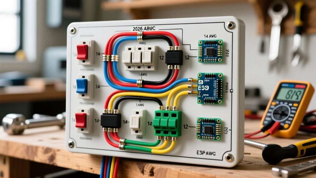
Automotive harnesses use strict color-coding standards, and the Kenmore 110 wiring diagram is no different. Understanding these pathways is critical before you even unplug the machine.
High-Voltage "Powertrain" Circuits (240V)
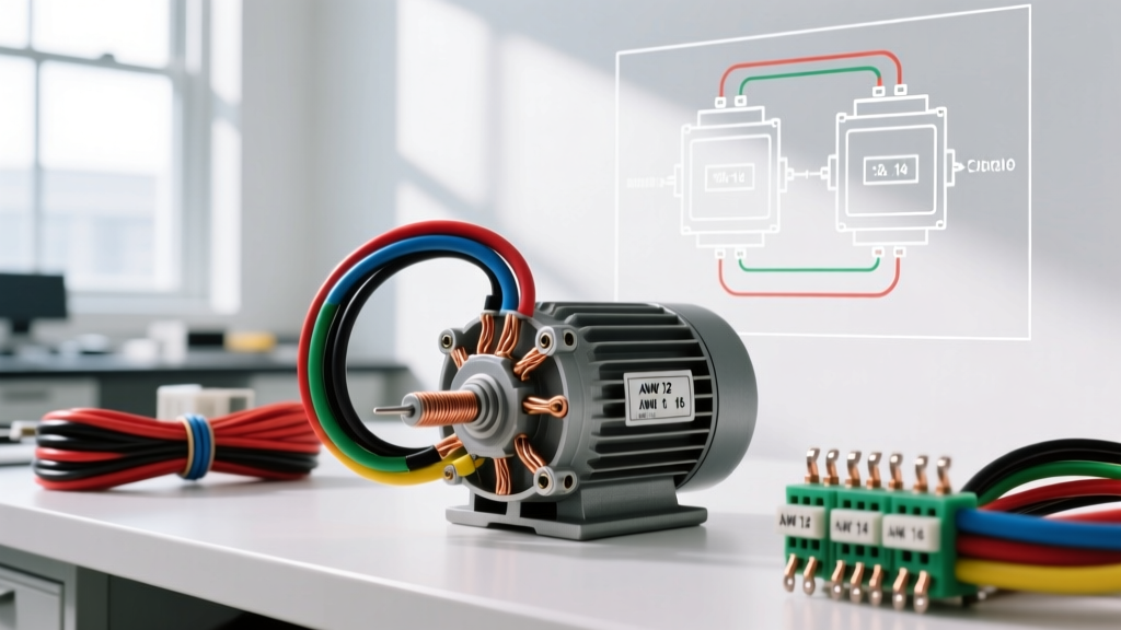
The heating element is the highest-draw component on the chassis, pulling roughly 18 to 22 amps. On the schematic, trace the Red and Black wires. These are your L1 and L2 feeds. In an automotive context, think of these as the heavy-gauge battery cables feeding the starter and alternator. Any corrosion on the spade connectors here will cause a massive voltage drop, leading to extended dry times that mimic a failing heating element.
Low-Voltage "Accessory" Circuits (120V)
The drive motor, timer motor, and interior light operate on 120V. They utilize one 120V leg (usually Red or Black) paired with the White neutral wire. If the drum light works but the motor hums without turning, your L1 feed is intact, but your "starter circuit" (centrifugal switch or start capacitor) is failing.
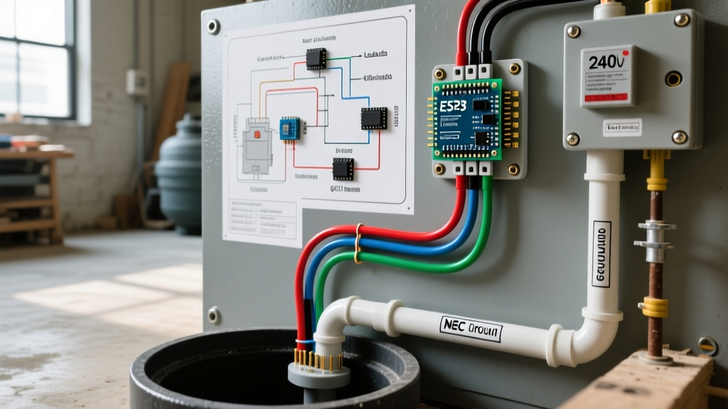
Expert Diagnostic Note: Never assume the chassis ground is clean. According to the NFPA 70 (National Electrical Code) Article 250, equipment grounding conductors must provide a permanent, low-impedance path. In the Kenmore 110, the Green wire bonds the motor casing and drum chassis to the terminal block. A loose ground here can cause the electronic control board to read phantom voltage spikes, throwing false F-01 or F-02 error codes.
The Information Gain: Live Voltage-Drop Testing
Most appliance repair guides tell you to unplug the dryer and test the heating element for continuity. This is a flawed, outdated approach. A heating element can show perfect continuity (approx. 10-15 Ohms) on a multimeter but still fail under load due to micro-fractures that expand when heated. Automotive technicians use Live Voltage-Drop Testing to find these hidden faults.
Step-by-Step Voltage Drop Procedure
- Safety First: Wear insulated gloves. Set your digital multimeter (a 2026-era Fluke 88V or equivalent automotive DVOM, retailing around $450) to AC Volts.
- Access the Harness: Remove the rear access panel to expose the terminal block and heating element housing.
- Apply Load: Plug the dryer in, set it to "Timed Dry - High Heat," and press start.
- Measure L1 to Element: Place one probe on the L1 terminal block post and the other on the heating element terminal. A reading above 0.5V AC indicates high resistance in the wire or the operating thermostat.
- Measure L2 to Element: Repeat on the L2 side, probing through the thermal fuse and high-limit thermostat. Again, any drop over 0.5V AC pinpoints the exact failing component without ever removing it from the chassis.
For a comprehensive guide on setting up your meter for this type of advanced continuity and voltage testing, reference the Fluke Best Practices Guide for Multimeters.
Diagnostic Matrix: Harness Pinout & Resistance Values
Use this reference matrix when probing the Kenmore 110 harness connectors. These values assume the circuit is isolated (unplugged) and at room temperature (approx. 70°F).
| Circuit Path | Wire Color | Automotive Equivalent | Expected Ohms (Ω) | Failure Symptom |
|---|---|---|---|---|
| L1 to Timer / Control Board | Red (Tan) | Main Ignition Feed | < 0.2Ω | Dead console, no lights |
| Motor Centrifugal Switch (Start) | Blue / White | Starter Relay Coil | 4.0Ω - 6.0Ω | Motor hums, drum won't spin |
| Heating Element Assembly | Red / Black | High-Draw Load (Alternator) | 10.0Ω - 15.0Ω | Runs but produces zero heat |
| Thermal Fuse (Exhaust) | White (Inline) | Main Fusible Link | 0.1Ω (Closed) | Complete chassis shutdown |
| Chassis Ground Bond | Green / Bare | Frame Ground Strap | 0.0Ω | Stray voltage, ECU faults |
Common Edge Cases & "Ghost" Electrical Faults
When tracing the wiring diagram for Kenmore dryer model 110, you will occasionally encounter "ghost" faults—symptoms that point to one component but are actually caused by a secondary harness issue.
The "Blown Thermal Fuse" Loop
If you replace the thermal fuse (part #3392519, approx. $12) and it blows again within three cycles, do not assume you received a bad batch of fuses. In automotive terms, this is equivalent to a shorted wiring harness repeatedly blowing a 15A fuse. The root cause is almost always a restricted exhaust chassis or a failing cycling thermostat (part #3387134) that is stuck closed, failing to cycle the heating element off before the exhaust plenum reaches the 250°F failsafe threshold.
The Door Switch Parasitic Draw
The door switch acts as a primary safety interlock, much like an automotive brake light switch preventing the cruise control from engaging. If the internal contacts of the door switch become pitted, it can create a high-resistance bridge. The control board will sense that the door is closed, but the voltage reaching the drive motor will drop below the 110V threshold required to engage the start winding. Always back-probe the door switch harness while the button is depressed to verify a clean 120V pass-through.
Sourcing Schematics and OEM Harness Data
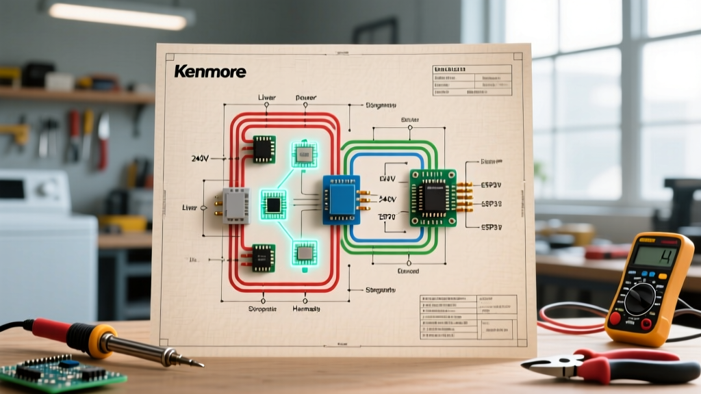
To view the exact schematic for your specific 110 sub-model (e.g., 110.62812990 or 110.87027700), you must reference the tech sheet hidden inside the dryer's console or lower front kick-panel. If the physical paper is degraded, digital OEM schematics can be sourced directly via Sears Parts Direct or the Whirlpool service portal using your exact 10-digit model number.
Final Safety Protocols
Before performing any invasive harness probing or component replacement, treat the appliance like a high-voltage EV chassis: disconnect the primary power source at the breaker panel, and use a non-contact voltage tester to verify zero energy state at the terminal block. Proper application of automotive-style wiring diagnostics will save you hundreds of dollars in misdiagnosed parts and ensure your Kenmore 110 runs reliably for years to come.