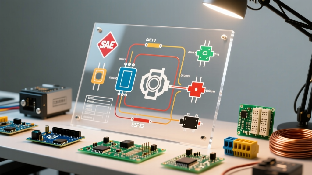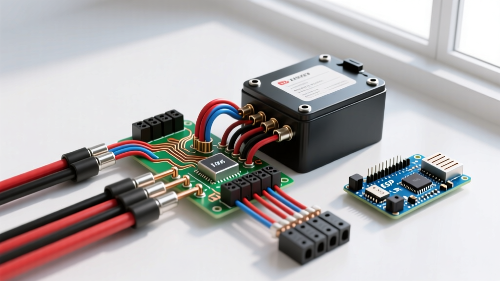

Decoding the Electric Scooter Battery Wiring Diagram
Building or repairing a high-capacity 48V lithium-ion pack requires more than just connecting positive to negative terminals. The electric scooter battery wiring diagram serves as the critical blueprint for integrating the cell matrix with the Battery Management System (BMS). According to the National Fire Protection Association (NFPA), improperly wired micromobility batteries remain a leading cause of thermal runaway in urban environments. This tutorial dissects a professional-grade 13-series (13S), 4-parallel (4P) wiring architecture using 21700 cells and a Smart BMS, providing the exact specifications and routing sequences required for a safe, high-performance build.
Core Component Specifications & 2026 Pricing
Before tracing the wiring diagram, you must select components capable of handling the high discharge rates typical of modern electric scooters (often peaking between 25A and 35A during hill climbs). Below is the exact bill of materials for a premium 48V (nominal) 16.8Ah pack.
| Component | Specification | Est. Cost (2026) | Engineering Purpose |
|---|---|---|---|
| Li-ion Cells | Molicel P42A 21700 (52x) | $338.00 | Energy storage (4200mAh/cell, 45A max discharge) |
| BMS | Daly 13S 48V 30A Smart | $55.00 | Cell balancing, over-current, and thermal protection |
| Nickel Strip | Pure Ni 0.15mm x 27mm | $25.00 | Low-resistance parallel/series cell interconnects |
| Main Wire | 10 AWG Silicone Copper | $18.00 | High-current discharge routing to the controller |
| Connector | Amass XT90-S (Anti-Spark) | $8.50 | Prevents voltage spikes from damaging the ESC |
Understanding the 13S4P Topology
A standard 48V electric scooter battery actually operates between 42V (depleted) and 54.6V (fully charged). To achieve this, the wiring diagram utilizes a 13S configuration (13 cells in series, multiplying the 4.2V max charge by 13). By placing 4 cells in parallel (4P) for each series group, we multiply the capacity and current-handling capability. As detailed in Battery University's guide on C-Rates, keeping the continuous discharge draw well below the cell's maximum C-rating drastically extends the cycle life and minimizes voltage sag under heavy acceleration.
Visualizing the Wiring Diagram: Phase 1 & 2
Phase 1: Cell Matrix and Spot Welding
The foundation of the wiring diagram is the physical cell matrix. Cells are arranged in alternating polarity blocks. Pure nickel strips (0.15mm thick) are spot-welded to connect the 4 parallel cells in each group, and then thicker nickel links bridge the series connections. Critical Edge Case: Never use nickel-plated steel strips. They possess higher internal resistance, which generates excessive heat at 30A draws. You can verify pure nickel by performing a spark test with an angle grinder—pure nickel produces dull, short orange sparks, while steel produces bright, branching white sparks.
Phase 2: The BMS Balance Harness Routing
This is where 90% of DIY builders destroy their BMS. The electric scooter battery wiring diagram requires the balance wires to be routed in a highly specific sequence. The Daly 13S BMS uses a 14-pin balance connector.
- Pin 1 (B-): Solder the black 22 AWG wire directly to the main negative busbar of the first parallel group (Group 1).
- Pins 2 through 13 (B1 to B12): Solder sequentially to the positive busbar of Group 1, positive of Group 2, all the way to the positive busbar of Group 12.
- Pin 14 (B+ / B13): Solder to the main positive busbar of the final series group (Group 13).
WARNING: Never plug the balance harness into the BMS while soldering. A momentary slip of the soldering iron bridging two adjacent balance wires will instantly fry the BMS internal resistors. Always solder, verify continuity with a multimeter, and plug in last.
Main Discharge and Charge Wiring Sequence
Once the balance harness is secured, the main power pathways must be established according to the diagram's high-current routing rules.
- Main Negative (C- / P-): The heavy 10 AWG black wire from the BMS 'P-' (Discharge Negative) pad solders directly to the XT90-S negative terminal. The BMS 'C-' (Charge Negative) pad wires to the DC5521 charge port negative.
- Main Positive (B+): The main positive from the battery pack (Group 13 positive busbar) bypasses the BMS entirely and routes directly to the XT90-S positive terminal and the charge port positive. The BMS only switches the negative leg in this common-port/split-port configuration.
According to the U.S. Department of Energy, maintaining low-resistance pathways in high-draw lithium-ion applications is vital for thermal stability. Using 10 AWG silicone wire ensures that even at a continuous 30A draw, the voltage drop across the main wires remains under 0.1V, preventing the wire insulation from melting and keeping the battery temperature within safe operating limits.
Troubleshooting Common Wiring Diagram Failures
Even with a perfect schematic, physical execution can introduce faults. Here is how to diagnose the most common anomalies when testing your newly wired scooter battery.
1. BMS Refuses to Output Power (No Voltage at XT90)
Cause: The BMS has tripped its short-circuit protection or is in an undervoltage lockout state because it hasn't detected the charge voltage.
Solution: Plug the battery into the 54.6V charger. The incoming charge voltage 'wakes up' the BMS MOSFETs. If using a Smart BMS, connect via Bluetooth to check the fault log and manually clear the protection flag.
2. Severe Voltage Sag Under Load
Cause: High internal resistance in the cell matrix, usually caused by weak spot welds or the use of undersized nickel strips.
Solution: Perform a voltage drop test across individual parallel groups while applying a dummy load. If one group drops significantly more than the others, grind off the nickel strip, clean the cell terminals with isopropyl alcohol, and re-weld using higher pulse current settings.
3. Chronic Cell Imbalance (BMS Halts Charging Early)
Cause: A broken strand of copper inside one of the 22 AWG balance wires, causing the BMS to read a 'ghost' voltage for that specific cell group.
Solution: Unplug the harness from the BMS. Use a multimeter to probe the pins on the soldered harness connector. If Pin 6 reads 0V relative to Pin 5, you have a broken wire. Re-solder the connection and secure the harness with Kapton tape to prevent vibration fatigue inside the scooter's battery enclosure.
Final Safety and Enclosure Integration
Wiring the battery is only half the battle; securing it within the scooter chassis dictates its long-term survival. Electric scooters endure immense vibration and shock. All main 10 AWG wires must be secured with adhesive-backed cable tie mounts and wrapped in high-temperature fiberglass sleeving. The BMS should be wrapped in Kapton tape and insulated with 1mm thick epoxy board (FR4) to prevent any accidental contact between the BMS component legs and the battery's nickel busbars.
By strictly adhering to this electric scooter battery wiring diagram and utilizing premium, verified materials, you ensure a power system that delivers reliable torque, maximizes range, and most importantly, operates safely for thousands of charge cycles.