
Mastering the NEC-Compliant Wiring Diagram for Submersible Well Pump Systems
Installing a submersible well pump requires far more than simply dropping a motor into a borehole and connecting it to a breaker. Water and high-voltage electricity are an unforgiving combination, and improper wiring remains a leading cause of premature motor failure, electrical shock hazards, and well casing fires. As jurisdictions across the country continue to adopt the 2023 and 2026 National Electrical Code (NEC) cycles, understanding the precise wiring diagram for submersible well pump configurations—and the code compliance surrounding them—is non-negotiable for professional installers and advanced DIYers.
This comprehensive guide breaks down the electrical schematic for 2-wire and 3-wire submersible systems, details exact conductor sizing per NEC Article 430, and outlines the critical grounding and splicing protocols required to pass inspection and ensure a 15-to-20-year motor lifespan.
The Core Wiring Diagram: 2-Wire vs. 3-Wire Systems
Before pulling wire through the conduit, you must identify whether your system utilizes a 2-wire or 3-wire motor configuration. The wiring diagram for a submersible well pump changes drastically between the two.
2-Wire Motor Configuration (Capacitor-Start/Internal Relay)
In a 2-wire system, the start capacitor and potential relay are sealed inside the motor housing. The wiring diagram is straightforward:
- Black Wire: Line 1 (Hot)
- White Wire: Line 2 (Hot - must be re-identified with black or red phase tape at both ends per NEC 200.7)
- Green/Bare Wire: Equipment Grounding Conductor (EGC)
Pros/Cons: While easier to wire and requiring no external control box, 2-wire motors have lower starting torque and are generally limited to 1.5 HP or less. If the internal capacitor fails, the entire motor must be pulled from the well.
3-Wire Motor Configuration (External Control Box)
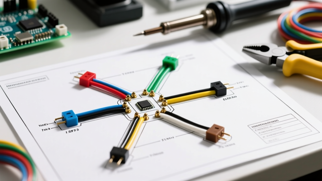
For higher horsepower applications (like the popular Franklin Electric 1 HP 3-Wire models), the start components are housed in an above-ground control box. The wiring diagram for this submersible well pump setup requires a 4-conductor cable (3 current-carrying + 1 ground):
- Black Wire: Main Winding (Run)
- Red Wire: Start Winding
- Yellow Wire: Common Winding
- Green Wire: Equipment Ground
The control box routes the red wire through the start capacitor and potential relay, providing a massive phase-shifted torque boost during the critical first 0.5 seconds of startup before dropping the start winding out of the circuit.
NEC Code Compliance: Conductor Sizing and Overcurrent Protection
The most common code violation in well pump installations is undersizing the branch circuit conductors or misapplying overcurrent protection. Submersible motors draw high Locked Rotor Amps (LRA) during startup. Sizing must comply with NFPA 70 (NEC) Article 430.
Wire Gauge and Breaker Sizing Matrix (230V Systems)
The following table outlines minimum copper conductor sizes for a standard 100-foot run, alongside the maximum inverse-time circuit breaker sizes permitted by NEC 430.52 (which allows up to 250% of the Full Load Amps to accommodate startup surges).
| Motor HP | Voltage | Full Load Amps (FLA) | Min Copper Wire (100ft) | Max Inverse Time Breaker |
|---|---|---|---|---|
| 1/2 HP | 230V | 7.6 A | 14 AWG | 20 A |
| 3/4 HP | 230V | 10.0 A | 12 AWG | 25 A |
| 1 HP | 230V | 13.2 A | 10 AWG | 30 A |
| 1.5 HP | 230V | 18.4 A | 8 AWG | 40 A |
| 2 HP | 230V | 24.0 A | 6 AWG | 60 A |
⚠️ Voltage Drop Warning: NEC 310.15 provides ampacity tables, but it does not account for voltage drop. For submersible pumps, a voltage drop exceeding 5% during operation (or 10% during startup) will cause severe overheating and dielectric breakdown of the motor windings. For runs exceeding 150 feet, always upsize the wire by at least one gauge. Use UF-B (Underground Feeder) or THWN-2 in PVC conduit for the trench, and standard submersible drop cable inside the well casing.
Grounding and Bonding: NEC Article 250 Requirements
A proper wiring diagram for a submersible well pump is useless if the grounding path is compromised. The NEC mandates two distinct grounding/bonding actions for well systems:
- Motor Grounding (NEC 250.112(D)): The pump motor must be grounded via an Equipment Grounding Conductor (EGC) run with the circuit conductors. This green wire connects to the motor chassis and terminates at the main panel's ground bar.
- Well Casing Bonding (NEC 250.112(F)): The metal well casing itself must be bonded to the electrical grounding system. This is achieved by attaching a listed bronze or copper ground clamp (e.g., Harger HDB20) to the steel casing below the frost line, connected via a minimum 6 AWG bare copper wire to the building's grounding electrode system or the panel's ground bar.
Expert Insight: Never rely on the metal well casing acting as a grounding electrode in lieu of an EGC. Soil resistivity varies wildly, and a fault inside the well could energize the casing if a dedicated copper EGC is not present.
The GFCI Nuance for Hardwired Well Pumps
A frequent question among electricians in 2026 is whether Ground Fault Circuit Interrupter (GFCI) protection is required on the well pump breaker. Under NEC 210.8(F), GFCI protection is required for outdoor receptacles. However, a hardwired submersible well pump on a dedicated branch circuit is generally exempt from GFCI requirements under this specific article.
Furthermore, applying a GFCI breaker to a deep-well submersible motor often results in nuisance tripping due to the natural capacitive leakage current of long drop cables submerged in mineral-rich water. Unless local municipal amendments explicitly override the NEC and mandate GFCI for hardwired agricultural or residential wells, standard inverse-time breakers combined with a robust EGC remain the code-compliant standard.
Waterproof Splicing: Preventing the #1 Failure Mode
The most common cause of submersible pump failure is not a burnt motor, but a failed splice allowing water ingress, which immediately shorts the windings to ground. Standard wire nuts and electrical tape will fail under hydrostatic pressure at 200 feet.
The Industry-Standard Splice Protocol:
- Strip 1 inch of insulation from the drop cable and motor leads.
- Connect using copper crimp sleeves or a high-quality solder joint. Do not use twisted wire nuts.
- Wrap the connection tightly with 3M ScotchKast 2228 mastic rubber tape, stretching it to 3/4 of its width to force the mastic into the wire strands.
- Overwrap with two layers of 3M Super 88 or Super 33+ vinyl electrical tape, extending 2 inches past the mastic on both sides to seal out moisture.
- Alternatively, use adhesive-lined, marine-grade heat shrink tubing with an internal polyamide sealant, applied with a propane torch.
Pre-Installation Megger Testing: A Mandatory Safety Step
Before lowering the pump into the borehole, you must verify the integrity of the motor windings and the drop cable. According to OSHA electrical safety guidelines and manufacturer specifications, insulation resistance testing is critical.
Using a megohmmeter (such as the Fluke 1587 FC Insulation Multimeter), set the tester to 500V DC. Test between each current-carrying conductor and the equipment ground:
- Black to Ground
- Red to Ground (or White to Ground on 2-wire)
- Yellow to Ground (3-wire only)
Passing Criteria: A healthy new motor and cable assembly should read greater than 100 Megohms (MΩ). If the reading is below 2 MΩ, you have a nicked cable jacket, a compromised factory seal, or a failed splice. Do not drop the pump. Troubleshoot the splice or replace the cable.
Conclusion: Safety Through Precision
Executing a safe, code-compliant wiring diagram for a submersible well pump requires strict adherence to NEC Article 430 for motor circuits and Article 250 for grounding. By properly sizing conductors to mitigate voltage drop, executing hydrostatic-proof splices, and bonding the well casing, you ensure a system that delivers reliable water pressure while protecting human life. For further education on residential electrical safety and grounding principles, consult resources provided by the Electrical Safety Foundation International (ESFI). Always pull local permits and have your trench and panel connections inspected by your local Authority Having Jurisdiction (AHJ) before backfilling or energizing the system.