
Decoding the Maytag Electric Dryer Wiring Diagram: An Expert Reference
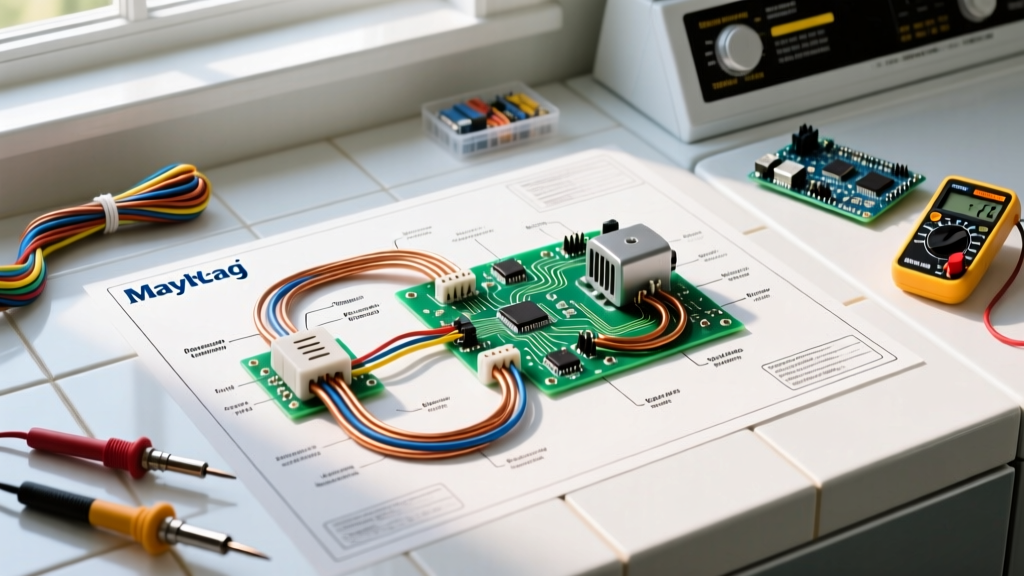
Maytag, now a flagship appliance brand under the Whirlpool Corporation, utilizes highly standardized ladder-style wiring diagrams across its electric dryer lineup. Whether you are servicing a classic mechanical-timer model or a 2026 smart-enabled unit like the Maytag MED6230HW or MED5030MW, the foundational logic of the schematic remains consistent. For DIYers and appliance technicians alike, the ability to read a Maytag electric dryer wiring diagram is the difference between blindly swapping parts and executing precise, cost-effective diagnostics.
Before touching a single wire, safety is paramount. Electric dryers operate on a 240-volt split-phase circuit, which carries enough amperage to be instantly lethal. Always adhere to OSHA's Control of Hazardous Energy guidelines by flipping the dedicated double-pole breaker in your main service panel and applying a physical lockout/tagout device before removing the rear or front access panels.
Anatomy of a Maytag Schematic: The Ladder Logic
Maytag wiring diagrams are drawn in a 'ladder' format. Imagine a ladder standing upright: the two vertical rails represent your power sources, and the horizontal rungs represent individual circuits.
- Left Rail (L1): Typically represents one leg of the 240V supply (120V to ground).
- Right Rail (L2 or N): Represents the second 240V leg for heating circuits, or the Neutral wire for 120V control and motor circuits.
- Rungs: Each horizontal line traces a specific path from L1 to L2 (or Neutral). If any switch or component on that rung is open, the circuit is broken, and the component will not energize.
Standard Component Symbols and Expected Readings
To troubleshoot effectively, you must know what the schematic symbols represent and how to verify them with a multimeter. Below is a reference matrix for the most critical components found on a Maytag dryer schematic.
| Component | Schematic Symbol | Expected Multimeter Reading | Common Failure Mode & Symptom |
|---|---|---|---|
| Heating Element | Zig-Zag Line | 10 - 15 Ω (Ohms) | Open circuit (infinite Ω). Symptom: Dryer runs, no heat. |
| Thermal Fuse | Rectangle with diagonal line | 0 Ω (Continuity) | Blown (infinite Ω) due to restricted venting. Symptom: Dead dryer or no heat. |
| Cycling Thermostat | Circle with internal contacts | 0 Ω (Closed when cold) | Welded contacts. Symptom: Dryer overheats and destroys clothes. |
| High-Limit Thermostat | Circle with 'H' or temp rating | 0 Ω (Closed when cold) | Tripped open from overheating. Symptom: No heat. |
| Centrifugal Switch | Switch tied to motor symbol | 0 Ω (When motor spins) | Stuck open. Symptom: Motor runs, but heating element never engages. |
| Push-to-Start Switch | Normally Open (NO) pushbutton | Infinite Ω (Open at rest) | Internal contacts burned. Symptom: Dryer won't start when button pressed. |
Step-by-Step Diagram Tracing for Common Failures
The true power of the Maytag electric dryer wiring diagram is revealed when you trace a circuit path to isolate a fault. Let us break down the two most common service calls.
Scenario 1: The Dryer Tumbles But Will Not Heat
The heating circuit in a Maytag dryer requires the full 240V potential (L1 to L2) and relies on a brilliant safety feature: the motor centrifugal switch. This switch ensures the heater only turns on when the drum is actively spinning, preventing a fire if the drive belt snaps.
- Trace the Path: Locate the heating rung on the diagram. Power flows from L1 (Red wire) → Timer or Electronic Control Board → Cycling Thermostat → High-Limit Thermostat → Heating Element → Thermal Fuse → Motor Centrifugal Switch → L2 (Black wire).
- Test the Thermal Fuse: Unplug the dryer. Locate the thermal fuse on the blower housing. Remove the wires and test for continuity. If it reads infinite resistance, the fuse is blown. Expert Note: A blown thermal fuse is a symptom, not the root cause. You must check the exhaust vent for lint buildup, as restricted airflow causes the high-limit thermostat to trip and blow the fuse.
- Test the Element: Disconnect the wires from the heating element terminals. Measure across the terminals. A reading of 10 to 15 ohms indicates a healthy element. If it reads 'OL' (Open Loop), the internal coil is broken, and the element must be replaced.
- Verify the Centrifugal Switch: If the fuse and element are good, the issue is often the centrifugal switch located inside the drive motor assembly. If this switch fails to close when the motor reaches operating RPM, the L2 path to the heater remains open.
Scenario 2: The Dryer is Completely Dead (Won't Start)
When a Maytag dryer refuses to start and the interior light is also dead, you are likely dealing with a 120V control circuit failure on the Neutral side.
- Trace the Path: Power flows from L1 → Timer/Control Board → Door Switch → Push-to-Start Switch → Motor Windings → Neutral (White wire).
- Check the Door Switch: The schematic shows this as a normally open switch that closes when the door is shut. Use your multimeter to test for continuity across the door switch terminals while pressing the plunger. Replace if open.
- Check the Thermal Fuse: On many Maytag models, the thermal fuse is wired in series with the motor's neutral path. If the fuse blows, the motor will not receive the neutral return, rendering the dryer completely dead.
Expert Insight: Never bypass a thermal fuse or high-limit thermostat to 'test' if the dryer will run. According to data from the U.S. Consumer Product Safety Commission (CPSC), dryers are a leading cause of residential structure fires. Bypassing safety thermostats removes the only barrier between a clogged vent and a catastrophic lint fire.
Advanced Diagnostics: Electronic Control Board (ECB) Pinouts
Modern Maytag dryers, such as the 2025/2026 MED6230HW, have replaced mechanical timers with Electronic Control Boards (ECBs). The wiring diagram for these models features a 'Pinout Matrix' rather than a traditional ladder.
When troubleshooting an ECB, you are testing inputs and outputs. For example, if the dryer won't heat, you must verify that the ECB is sending 120V to the heater relay. Using a digital multimeter set to AC Volts, carefully back-probe the harness connector at the ECB. If the ECB receives 120V input on Pin 1 (L1) and the thermistor input on Pins 4 and 5 reads the correct resistance for room temperature (typically around 50k Ω at 77°F), but Pin 3 (Heater Relay Out) outputs 0V when a heat cycle is selected, the ECB's internal triac has failed, and the board must be replaced.
Decoding Maytag Wire Color Standards
While you should always rely on the specific schematic tucked inside the dryer's control panel console, Maytag/Whirlpool adheres to a strict internal wire color code that speeds up visual diagnostics:
- Red & Black: 240V Main Power Lines (L1 and L2).
- White: 120V Neutral Return.
- Green or Bare Copper: Chassis Ground.
- Blue: 120V Control Circuits (Timer motors, interior lights, push-to-start).
- Orange or Yellow: 240V Heating Circuits (Connecting the element to the thermostats).
NEC Compliance: 4-Prong vs. 3-Prong Terminal Block Wiring
When installing or relocating a Maytag dryer, referencing the wiring diagram on the terminal block cover is legally and functionally critical. Under the National Electrical Code (NEC) Article 250.140, as outlined by the National Fire Protection Association (NFPA), new installations must utilize a 4-prong cord and receptacle.
The Crucial Difference:
- 3-Prong (Older Homes): The neutral and ground are bonded together at the dryer's terminal block using a metal grounding strap. The neutral carries the 120V return current and acts as the safety ground.
- 4-Prong (Modern Standard): The neutral and ground are strictly separated. The grounding strap on the Maytag terminal block must be removed and folded back, or the dryer's chassis will become energized with 120V return current, creating a severe shock hazard. The white neutral wire connects to the center terminal, the red and black hot wires to the outer terminals, and the green ground wire attaches directly to the dryer's metal chassis ground screw.
Frequently Asked Questions (FAQ)
Where can I find the exact wiring diagram for my specific Maytag model?
Maytag includes a schematic inside a hidden envelope. Depending on your model, this is typically located inside the console control panel (behind the backguard), taped to the inside of the lower front kick-panel, or tucked into the rear access panel. Always use the factory-provided diagram rather than a generic internet image, as engineering revisions change wire routing even within the same model year.
My multimeter reads 240V at the wall outlet, but the dryer is dead. What does the diagram suggest?
If you have verified 240V at the receptacle, trace the L1 and L2 paths from the terminal block to the Electronic Control Board or Timer. A common failure point is the terminal block itself; loose screws can cause arcing, melting the plastic block and severing the connection before power reaches the internal components.
Can I use a standard 120V extension cord to test the dryer motor?
No. The Maytag schematic shows the drive motor is designed to operate on 120V, but it requires the specific phase relationship and amperage capacity provided by the main harness. Furthermore, attempting to bypass the main harness to bench-test the motor without the centrifugal switch properly engaged can result in immediate component damage or personal injury.