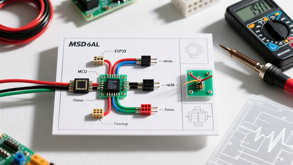

Understanding the Wiring Diagram for MSD 6AL: A Safety-First Approach
The MSD 6AL (Model 6425) and its successor, the 6AL-2 (Model 6465), remain legendary capacitive discharge (CD) ignition systems in both grassroots motorsports and street-performance builds. As of 2026, with the retail price of the 6425 hovering around $290 and the 6465 near $370, protecting your investment—and your vehicle—requires strict adherence to electrical safety codes. A standard wiring diagram for MSD 6AL units provides the basic pinout, but it rarely details the critical safety margins required to prevent electrical fires, EMI-induced ECU resets, or catastrophic ground-loop failures.
From the perspective of automotive safety and racing code compliance, installing a high-energy CD ignition box goes far beyond matching wire colors. This guide breaks down the exact wiring protocols, SAE (Society of Automotive Engineers) standards, and NHRA (National Hot Rod Association) safety regulations you must follow when wiring an MSD 6AL system.
Core Pinout and Safety Matrix
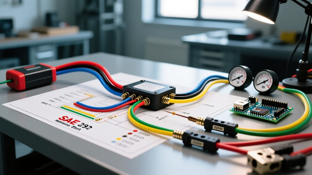
Before cutting or crimping a single wire, you must understand the current draw and signal sensitivity of each circuit. The MSD 6AL utilizes a mix of heavy-gauge power wires and light-gauge trigger/signal wires. Below is the safety-focused breakdown of the standard MSD 6AL harness.
| Wire Color | Function | Min. Gauge (SAE J1128) | Safety & Compliance Note |
|---|---|---|---|
| Heavy Red | Main 12V+ Power | 8 AWG | Must be fused within 7 inches of the battery positive terminal. |
| Heavy Black | Main Ground | 8 AWG | Must ground directly to the engine block or dedicated chassis stud. |
| Light Red | Switched 12V+ (Ignition) | 16 AWG | Triggers the box; do not splice into high-current accessory circuits. |
| White | Points/Condenser Trigger | 18 AWG | Sensitive to voltage spikes; requires a 0.47µF ballast resistor if using points. |
| Violet / Orange | Magnetic Pickup Trigger | 18 AWG (Shielded) | Must be routed away from spark plug wires to prevent EMI cross-talk. |
| Green | Tachometer Output | 18 AWG | Outputs a 12V square wave; use a pull-up resistor if feeding modern EFI ECUs. |
Wire Gauge Selection and SAE J1128 Compliance
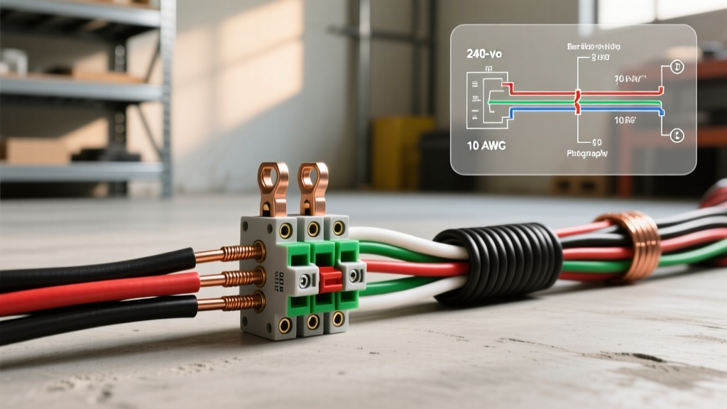
The most common failure mode in aftermarket ignition installations is the use of undersized power wire. The MSD 6AL can draw up to 15 amps continuously and spike to 30 amps during high-RPM multiple-spark sequences. According to SAE International standards, specifically SAE J1128 for low-tension primary cable, wire gauge must be selected based on both current draw and total run length to prevent excessive voltage drop.
The Voltage Drop Hazard
If you use 12 AWG wire for a 12-foot run from the battery to the ignition box, the resistance will cause a voltage drop exceeding 0.5 volts under load. When the vehicle's alternator output dips during heavy electrical loads (e.g., cooling fans and fuel pumps engaging simultaneously), the voltage at the MSD box can drop below 10.5 volts. This causes the internal microprocessor to reset, resulting in a sudden engine misfire or complete shutdown at high speed—a massive safety hazard on the track or highway.
- Runs under 8 feet: 10 AWG SAE J1128 compliant copper wire is acceptable.
- Runs over 8 feet: 8 AWG copper wire is mandatory to maintain a voltage drop below 3%.
- Wire Material: Never use Copper-Clad Aluminum (CCA) wire. CCA has higher resistance and is prone to galvanic corrosion at the crimp terminals, which can lead to arcing and under-hood fires.
Grounding Protocols: Eliminating Ground Loops
Improper grounding is responsible for over 70% of CD ignition noise and failure issues. The heavy black wire on the MSD 6AL must complete a high-current circuit back to the battery's negative terminal. Relying on factory chassis grounds, which are often painted or powder-coated, violates basic electrical safety codes.
Expert Rule of Thumb: Never ground high-amperage ignition components to sheet metal, intake manifolds, or cylinder heads secured by painted bolts. Always use a dedicated grounding stud welded or bolted to the engine block or main chassis rail.
Step-by-Step Compliant Grounding
- Surface Preparation: Use 80-grit sandpaper or a rotary wire brush to remove all paint, powder coat, and rust from the grounding surface until bare, shiny metal is exposed.
- Terminal Selection: Use a 3/8-inch ring terminal (never a spade terminal, which can vibrate loose). The terminal must be SAE J1123 compliant.
- Crimping: Use a Mil-Spec indent crimper. Smash crimpers do not provide the necessary cold-weld compression, leading to high-resistance joints that generate heat.
- Hardware: Secure the terminal using a Grade 8 bolt with a star washer (to bite into the metal) and a locking nylon-insert nut.
- Corrosion Protection: After tightening, coat the entire terminal and exposed bare metal with a dielectric grease or dedicated anti-corrosion compound to prevent moisture ingress and galvanic corrosion.
Routing, EMI, and Fire Safety Standards
The MSD 6AL generates massive electromagnetic interference (EMI) due to its high-voltage, high-frequency spark output. If the trigger wires (Violet/Orange or White) are routed parallel to the spark plug wires or the main alternator charging wire, the EMI can induce false trigger signals, causing the engine to backfire or over-rev past its mechanical limits.
Separation Distances and Shielding
To comply with best-practice automotive EMC (Electromagnetic Compatibility) guidelines, maintain a minimum separation of 6 inches between the MSD trigger wires and any high-voltage spark plug wires or high-current alternator cables. If crossing is unavoidable, the wires must cross at a strict 90-degree angle.
Furthermore, modern builds utilizing EFI systems (such as Holley Terminator X or Haltech Elite) require pristine tach signals. The green tach output wire from the MSD 6AL should be routed through a shielded cable sleeve if it must pass near the ignition coil or exhaust headers, preventing heat degradation and signal noise.
Firewall Pass-Through Compliance
When routing the heavy red and black wires through the vehicle's firewall, you must use a reinforced rubber or silicone grommet. Sheet metal edges will slice through SAE J1128 wire insulation over time due to engine vibration, creating a direct short to the chassis. A direct short from an unfused 8 AWG wire can instantly ignite the vehicle's wiring harness. Per SFI Foundation and NHRA safety guidelines, all wiring passing through structural bulkheads must be protected by approved pass-through grommets or bulkhead connectors.
Fusing and Overcurrent Protection (NHRA & ABYC Standards)
While the NHRA rulebook and marine ABYC (American Boat and Yacht Council) standards target different environments, their core philosophy regarding overcurrent protection is identical: The fuse must protect the wire, and it must be placed as close to the power source as possible.
Proper Fuse Sizing and Placement
The heavy red wire requires a 30-amp MAXI fuse or a 40-amp ANL fuse. However, the physical location of this fuse is a critical safety factor often ignored in generic wiring diagrams.
- The 7-Inch Rule: The fuse holder must be installed within 7 inches of the battery's positive terminal. If a short occurs between the battery and the ignition box, the fuse will blow before the wire can melt and start a fire.
- Relay Integration: If you are using a heavy-duty solenoid or relay to trigger the MSD box via the light red wire, the relay's main power feed must also be independently fused at the battery.
- Waterproofing: Use sealed, waterproof inline fuse holders (IP67 rated). Under-hood environments are exposed to high humidity, pressure washing, and temperature cycling, all of which can corrode standard plastic blade-fuse contacts, increasing resistance and causing premature fuse failure.
Modern EFI Integration: The 2026 Perspective
As of 2026, standalone CD ignitions are frequently paired with advanced drive-by-wire EFI systems. The interaction between the MSD 6AL's green tach output wire and modern ECUs requires specific attention to voltage pull-up circuits. Many modern ECUs expect a 5V square wave or a specific 12V edge-trigger signal. Feeding the raw MSD tach signal directly into an unprotected ECU input pin without verifying the ECU's internal pull-up resistor configuration can backfeed voltage, potentially frying the ECU's ignition input driver—a repair that can cost upwards of $1,200.
Always consult your specific ECU manufacturer's wiring addendum when integrating the MSD 6AL green wire. In many cases, installing a simple 1N4001 diode inline (with the stripe facing the ECU) acts as a one-way valve, protecting the ECU from voltage spikes generated by the CD box's internal capacitors.
Troubleshooting Common Safety Hazards
If your MSD 6AL installation is experiencing issues, avoid the temptation to simply 'upsizing' the fuse or bypassing safety circuits. Use this diagnostic checklist to identify the root cause safely:
- Symptom: Box gets excessively hot to the touch.
Hazard: The internal capacitors are overworking due to a weak ground or a failing ignition coil drawing excessive primary current. Check the resistance of your ignition coil (primary should be 0.5 to 1.0 ohms). A shorted coil will destroy the MSD box and pose a fire risk. - Symptom: Engine dies when cooling fans engage.
Hazard: Severe voltage drop on the main 12V feed. The cooling fans are pulling amperage through a shared, undersized chassis ground or power bus. Reroute the MSD heavy red wire directly to the battery or a dedicated front-mounted power distribution block. - Symptom: Tachometer bounces erratically at high RPM.
Hazard: EMI cross-talk on the green wire. Reroute the wire away from the exhaust and spark plug wires, and verify the tachometer is calibrated for a 12V square-wave signal, not a standard HEI or points signal.
Final Safety Verification Checklist
Before applying battery power to your newly wired MSD 6AL system, perform this final compliance check:
- Verify the main 30A/40A fuse is within 7 inches of the battery positive.
- Confirm all heavy gauge terminals are Mil-Spec crimped and heat-shrunk.
- Ensure the main ground is attached to bare, unpainted metal using a star washer.
- Check that all firewall pass-throughs utilize rubber grommets to prevent insulation chafing.
- Confirm trigger wires are routed at least 6 inches away from high-voltage spark plug wires.
By treating the wiring diagram for MSD 6AL not just as a connectivity map, but as a blueprint for electrical safety and code compliance, you ensure reliable, high-energy spark delivery while eliminating the risk of under-hood fires and catastrophic component failure.