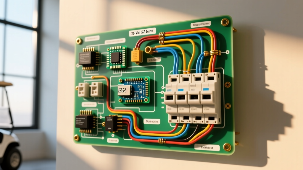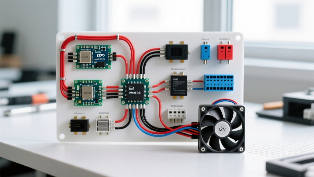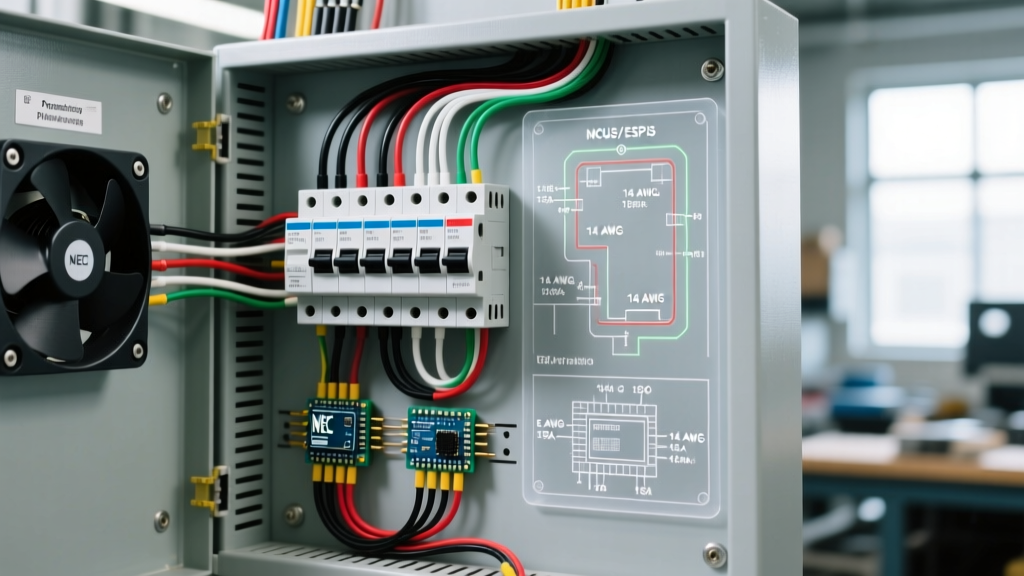

The Panel-First Approach to Electrical Fan Wiring
When most DIYers and junior electricians research electrical fan wiring, they immediately focus on the ceiling canopy, matching colored wires, and installing wall switches. However, a reliable, code-compliant installation begins at the breaker panel. Undersized breakers cause nuisance tripping, improper wire gauges create fire hazards via voltage drop, and ignoring Arc-Fault Circuit Interrupter (AFCI) mandates will result in a failed inspection. This guide approaches electrical fan wiring from the perspective of the panel and breaker, ensuring your circuit is properly sized, routed, and terminated before the first wire is ever stripped at the fan housing.
NEC Code Mandates for Fan Circuits
The National Electrical Code (NEC) treats fans not just as lighting fixtures, but as specific appliances and motors depending on their application. According to the National Fire Protection Association (NFPA 70), several critical articles govern how you wire and protect these circuits:
- NEC Article 422.12 (Ceiling Fans): While primarily focused on physical support (requiring boxes rated for 35+ lbs), it dictates that ceiling fans must be wired with methods suitable for the environment, including damp-rated wiring for outdoor pergolas or covered porches.
- NEC Article 210.12 (AFCI Protection): Any electrical fan wiring routed to a bedroom, living room, hallway, or family room must be protected by a Combination-Type AFCI breaker or receptacle. Standard thermal-magnetic breakers are no longer code-compliant for these living spaces.
- NEC Article 430 (Motors): Large whole-house fans and industrial exhaust fans fall under motor circuit rules, requiring specific overload protection and disconnecting means that standard residential lighting breakers do not provide.
Breaker Sizing and Wire Gauge Matrix
Selecting the correct wire gauge and breaker size is the foundation of safe electrical fan wiring. The table below outlines standard residential and light-commercial fan applications, factoring in continuous load rules and typical startup surges (Locked Rotor Amperage).
| Fan Application | Typical Amp Draw | Min. Wire Gauge (NM-B) | Breaker Size & Type | Circuit Requirement |
|---|---|---|---|---|
| Standard Ceiling Fan (w/ LED) | 0.5A - 1.5A | 14 AWG | 15A (AFCI if in living area) | Shared Lighting Circuit |
| Bathroom Fan/Heater (e.g., Broan 1500W) | 12.5A | 12 AWG | 20A (GFCI/AFCI Dual Function) | Dedicated Circuit Required |
| Whole-House Fan (1/2 HP Direct Drive) | 6A - 9A | 12 AWG | 15A or 20A Standard | Dedicated Circuit Recommended |
| Garage High-Velocity Pedestal Fan | 4A - 8A | 12 AWG | 20A Standard | Shared Receptacle Circuit |
| Outdoor Pergola Ceiling Fan | 1.0A - 2.0A | 12 AWG (UF-B) | 15A or 20A GFCI | Dedicated Outdoor Circuit |
Pro Tip: While 14 AWG wire is permissible for 15A ceiling fan circuits, many professional electricians exclusively use 12 AWG (12/2 NM-B) for all new branch circuits to future-proof the line and minimize voltage drop on long runs. As of 2026, 12/2 NM-B costs roughly $0.65 per foot, a marginal increase over 14 AWG ($0.45/ft) that pays off in safety and versatility.
Dedicated vs. Shared Circuits: When to Isolate
A common point of confusion in electrical fan wiring is determining when a fan requires a dedicated circuit straight from the panel.
When Sharing is Permitted
Standard ceiling fans without integrated heating elements can easily share a 15A or 20A lighting circuit. Because modern DC-motor ceiling fans (like the Haiku or Big Ass Fans models) draw less than 0.5 amps at maximum speed, you can theoretically wire a dozen of them on a single 15A breaker without approaching the 80% continuous load threshold (12A).
When Dedicated Circuits are Mandatory
Bathroom exhaust fans equipped with ceramic heater elements (such as the popular Broan NuTone QT9093WH) draw upwards of 12.5 amps when the heater is engaged. The NEC strictly prohibits sharing a bathroom heater circuit with general lighting. You must run a dedicated 12/2 NM-B cable from a 20A Dual Function (AFCI/GFCI) breaker directly to the fan's junction box. Attempting to share this circuit will result in immediate breaker trips when a hair dryer and the fan heater are used simultaneously.
Step-by-Step: Terminating the Fan Circuit at the Panel
Proper termination at the breaker panel ensures longevity and prevents arc faults. Follow these precise steps when landing your electrical fan wiring at the main service panel.
1. Breaker Selection and AFCI Pigtails
If your fan is located in a code-mandated AFCI zone, you will be installing a Combination AFCI breaker (e.g., Eaton BR115AFC or Square D HOM115AFCI, typically priced between $38 and $48). These breakers feature a coiled white neutral pigtail.
- Land the Pigtail First: Connect the breaker's white pigtail directly to the panel's neutral bar. Do not cut or extend this pigtail; doing so alters the internal sensing coil calibration.
- Connect the Circuit Neutral: The white wire from your 14/2 or 12/2 NM-B cable must terminate on the breaker's designated neutral screw terminal, not the panel's neutral bar. If you bypass the breaker's neutral terminal, the AFCI logic board will not have a complete circuit to monitor, and the breaker will trip immediately upon energization.
- Connect the Hot: Terminate the black circuit wire on the breaker's main hot lug.
2. Torque Specifications (The Hidden Failure Point)
Since the 2017 NEC update (and reinforced in 2023/2026 editions), all breaker and lug terminations must be torqued to the manufacturer's specifications using a calibrated torque screwdriver. Under-torqued lugs expand and contract with thermal cycling, eventually causing arcing and panel fires. For most standard 15A and 20A residential breakers, the hot lug requires 25 inch-pounds of torque, while the neutral bar screws require 20 inch-pounds. Always verify the exact spec printed on the breaker's schematic label.
Common Panel-Side Failure Modes and Troubleshooting
Even if the electrical fan wiring at the ceiling is flawless, panel-side errors will cripple the system. Watch out for these specific failure modes:
Nuisance Tripping on AFCI Breakers: If a newly wired bedroom ceiling fan trips the AFCI breaker instantly, check for a 'shared neutral' or 'borrowed neutral' in a junction box downstream. AFCI breakers monitor the exact current balance between the hot and neutral. If the neutral returns via a different circuit's neutral bar path, the breaker detects an imbalance and assumes an arc fault.
Voltage Drop in Detached Structures: Wiring a high-velocity exhaust fan in a detached garage or workshop requires running wire underground or overhead. If the run exceeds 100 feet from the main panel, standard 12 AWG wire will suffer from significant voltage drop, causing the fan motor to overheat and burn out prematurely. For runs over 100 feet, upsize your electrical fan wiring to 10 AWG (10/2 UF-B or THWN in conduit) to maintain voltage within the NEC-recommended 3% drop limit for branch circuits.
Frequently Asked Questions
Can I use a smart switch for my ceiling fan on an AFCI circuit?
Yes, but with caveats. Smart switches (like the Lutron Caseta Fan Control) require a neutral wire to power their internal Wi-Fi/Zigbee radios. Ensure your electrical fan wiring includes a 14/3 or 12/3 cable to the switch box to provide an always-hot, a switched-hot (or fan control leg), and a dedicated neutral. Furthermore, some smart switches generate high-frequency electrical noise that can cause overly sensitive older-generation AFCI breakers to trip. Upgrading to a 2023/2026 generation AFCI breaker usually resolves this software-filtering issue.
Do whole-house fans require special panel wiring?
According to the U.S. Department of Energy, whole-house fans are highly efficient but draw significant startup current. A standard 1/2 HP whole-house fan should be wired on a dedicated 15A or 20A circuit. Because these fans are often installed in attics, ensure the NM-B cable is routed through bored joist holes and secured within 8 inches of the fan's junction box, per NEC 334.30. If the fan is hardwired, a local disconnect switch must be installed within sight of the motor.
What wire do I use for a fan and light combo with two wall switches?
To independently control the fan motor and the light kit from two separate wall switches, your electrical fan wiring must utilize 14/3 NM-B (or 12/3 on a 20A circuit). The red and black wires act as the two separate 'hot' legs traveling from the dual switch box up to the ceiling canopy, while the white wire serves as the shared neutral. Ensure the ceiling box has adequate cubic inch volume to accommodate the extra wire fill; a standard 4-inch round box may be too small, necessitating a deeper pancake or fan-rated retrofit box.
By mastering the panel-side fundamentals of breaker sizing, AFCI integration, and torque specifications, your electrical fan wiring projects will not only pass inspection but will operate safely and reliably for decades. For more information on energy-efficient fan selections, refer to the ENERGY STAR ceiling fan guidelines to pair your robust electrical infrastructure with high-efficiency DC motors.