
Decoding the Solar Panel Wiring Diagram for Home Systems
Designing and executing a safe, code-compliant photovoltaic (PV) installation requires more than just mounting hardware; it demands a precise understanding of electrical routing. A comprehensive solar panel wiring diagram for home setups acts as the blueprint for transferring raw DC power from your roof to usable AC power in your main service panel (MSP). In 2026, with copper prices fluctuating and the National Electrical Code (NEC) enforcing stricter rapid shutdown and busbar interconnection rules, guessing your wire gauges or breaker sizes is both dangerous and illegal.
This step-by-step walkthrough dissects the standard string-inverter topology equipped with module-level power electronics (MLPE). We will cover the exact wire types, breaker sizing mathematics, and NEC 2023/2026 mandates you need to finalize your schematic and pass your local Authority Having Jurisdiction (AHJ) inspection.
Anatomy of a Standard Home Solar Wiring Diagram
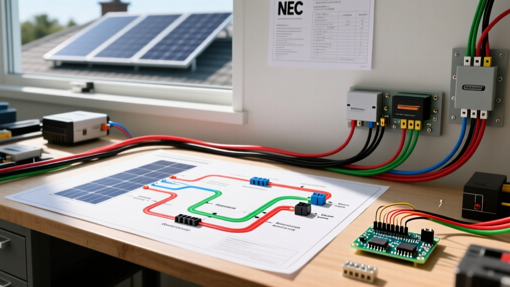
Before pulling a single foot of wire, you must understand the sequential flow of a residential solar diagram. A typical string-inverter system follows this exact path:
- PV Modules & DC Optimizers: Panels wired in series, each paired with a DC optimizer for module-level maximum power point tracking (MPPT) and rapid shutdown.
- DC Home Runs: Positive and negative PV wire traveling from the roof down to the inverter.
- DC Disconnect: A manual, lockable switch to isolate the inverter from the roof array.
- String Inverter: The central hub converting high-voltage DC (up to 600V) into 240V split-phase AC.
- AC Disconnect: A secondary lockable switch isolating the inverter from the home's grid.
- Main Service Panel (MSP) Interconnection: The final backfed breaker connecting solar production to your home's electrical busbar.
Step 1: Roof-Level DC Wiring and MLPE Integration
The DC side of your solar panel wiring diagram begins at the roof. Modern residential systems almost universally utilize DC optimizers (such as the SolarEdge S440 or Enphase IQ8 microinverters) to comply with NEC Article 690.12 Rapid Shutdown requirements. This code mandates that conductors outside the array boundary must be reduced to 30 volts or less within 30 seconds of shutdown initiation.
Selecting the Right DC Conductors
For the home runs connecting the optimizers to the DC disconnect, you must use 10 AWG or 12 AWG PV Wire. Do not use standard THHN/THWN-2 wire on the roof. PV wire is specifically formulated with cross-linked polyethylene (XLPE) insulation to withstand extreme UV radiation, ozone exposure, and 90°C wet-location temperatures.
- Connectors: Use only matching MC4 or Amphenol H4 connectors. Mating mismatched brands can cause micro-arcing, leading to localized melting and roof fires.
- Clipping & Routing: Secure PV wire every 12 to 18 inches using UV-rated stainless steel or black nylon zip ties. Never let the wire rest directly on the roof shingles or touch sharp metal flashing.
Step 2: Sizing DC and AC Wire Gauges
Voltage drop and ampacity dictate your wire sizing. According to industry best practices and the Department of Energy's solar installation guidelines, keeping voltage drop below 2% for DC and 3% for AC ensures maximum inverter efficiency. Below is a reference matrix for a standard 7.6kW to 10kW residential inverter setup (e.g., SolarEdge SE10000H or SMA Sunny Boy 7.7).
| Circuit Segment | Max Current (Amps) | Recommended Wire Gauge | Insulation Type | Conduit Fill Notes |
|---|---|---|---|---|
| Panel to Optimizer (Short Jumper) | 15A | 12 AWG | PV Wire (XLPE) | Exposed on roof rack |
| Optimizer to DC Disconnect | 20A | 10 AWG | PV Wire / THWN-2 | Transition to THWN-2 inside conduit |
| Inverter AC Output to AC Disconnect | 32A - 40A | 8 AWG or 6 AWG | THWN-2 | Max 40% conduit fill capacity |
| AC Disconnect to Main Panel | 40A - 50A | 6 AWG or 4 AWG | THWN-2 | Requires 4-wire setup if sub-panel |
| Grounding Electrode Conductor (GEC) | N/A | 8 AWG or 6 AWG | Bare Copper | Must be continuous, unspliced |
Step 3: AC Interconnection and NEC 705.12 Busbar Rules
The most critical math in your solar panel wiring diagram for home setups occurs at the Main Service Panel (MSP). You will be backfeeding power into the busbar via a dedicated solar breaker. This is governed by NEC Article 705.12(B), commonly known as the 120% Rule.
Calculating the Maximum Solar Breaker Size
The 120% rule states that the sum of the main breaker rating and the solar backfeed breaker rating cannot exceed 120% of the busbar's rated ampacity. Furthermore, the solar breaker must be placed at the opposite end of the busbar from the main utility breaker to prevent overloading the center of the metal busbar stabs.
Example Calculation for a 200A Main Panel:
Busbar Rating: 200A
120% of Busbar: 240A
Main Utility Breaker: 200A
Maximum Allowable Solar Breaker: 240A - 200A = 40A
If your inverter's maximum continuous output current is 32A, the NEC requires you to size the breaker at 125% of the continuous load (32A x 1.25 = 40A). In this scenario, a 40A breaker perfectly matches both the inverter's requirement and the busbar's 120% rule limit. If your calculation yields a non-standard breaker size (e.g., 38A), you must round up to the next standard size (40A), provided it doesn't violate the busbar limit. If it does, you must upgrade your MSP or install a line-side tap.
Step 4: Grounding, Bonding, and Equipment Safety
A complete wiring diagram must explicitly detail the grounding scheme. Solar systems require two distinct grounding paths:
- Equipment Grounding Conductor (EGC): This bonds all non-current-carrying metal parts (panel frames, racking, inverter chassis, disconnect enclosures) together. For a 40A circuit, a 10 AWG copper EGC is the minimum, but many installers upgrade to 8 AWG or 6 AWG to mitigate voltage spikes from nearby lightning strikes.
- Grounding Electrode Conductor (GEC): This connects the inverter's grounding busbar to the home's primary grounding electrode system (such as the Ufer ground or ground rods). Per NEC 250.66, an 8 AWG bare copper wire is typically sufficient for residential inverters, provided it is run in a continuous, unbroken path.
Pro-Tip: When terminating grounding wires in the inverter or disconnect, use an irreversible crimp connector or torque the lug to the manufacturer's exact specification. For example, SolarEdge specifies 2.5 Nm (22 in-lbs) for their AC terminal blocks. Under-torqued lugs cause high-resistance connections, leading to thermal runaway and melted terminals.
Step 5: Transitioning Through the Attic and Conduit
Running wire from the roof eave to the inverter location (often the garage or exterior side wall) requires transitioning from exposed PV wire to conduit-protected THWN-2.
- The Junction Box Transition: Install a NEMA 3R rated junction box at the soffit. Inside this box, splice the roof's PV wire to THWN-2 using insulated wire nuts or Wago lever connectors rated for the voltage.
- Conduit Sizing: For three 6 AWG THWN-2 current-carrying conductors plus a 10 AWG ground, a 1-inch PVC Schedule 80 or EMT conduit is required to maintain the 40% fill ratio mandated by NEC Chapter 9, Table 1.
- Condensation Management: Always install weep holes at the lowest points of exterior conduit runs and use duct seal at the MSP entry point to prevent moisture from migrating into your main electrical panel.
Frequently Asked Questions (FAQ)
Can I use standard Romex (NM-B) wire for the AC solar run?
Only if the entire run is indoors, inside a climate-controlled space, and protected from physical damage. However, because most solar AC runs travel along exterior walls or through attics that exceed 86°F (30°C), THWN-2 inside conduit is vastly superior. NM-B insulation degrades rapidly under high attic heat, and applying the NEC 310.15 temperature correction factors often forces you to upsize Romex by two full gauges compared to THWN-2.
Do I need a separate DC and AC disconnect in 2026?
It depends on your local AHJ and the inverter model. Many modern string inverters feature integrated, lockable DC and AC disconnects, satisfying NEC requirements without needing standalone exterior boxes. Always verify this with your local building department before finalizing your solar panel wiring diagram for home submission.
What happens if my main panel is maxed out and fails the 120% rule?
If your busbar cannot accommodate the required solar breaker, you have three options: perform a heavy-up upgrade to a 400A MSP, install a line-side tap (splicing directly between the utility meter and main breaker), or install a sub-panel dedicated to solar and critical loads. For deeper insights on grid interconnection, refer to the Department of Energy's planning resources.
Finalizing Your Diagram for Inspection
Your final solar panel wiring diagram for home submission to the city or county permitting office must include a single-line diagram (SLD). This SLD should clearly label every overcurrent protection device (OCPD), wire gauge, conduit type, and disconnect rating. By adhering strictly to the NEC ampacity derations, the 120% busbar rule, and proper MLPE integration, your system will not only pass inspection on the first attempt but will operate safely and efficiently for its entire 25-year warranted lifespan.