
The Intersection of Outboard Power and Marine Breaker Panels
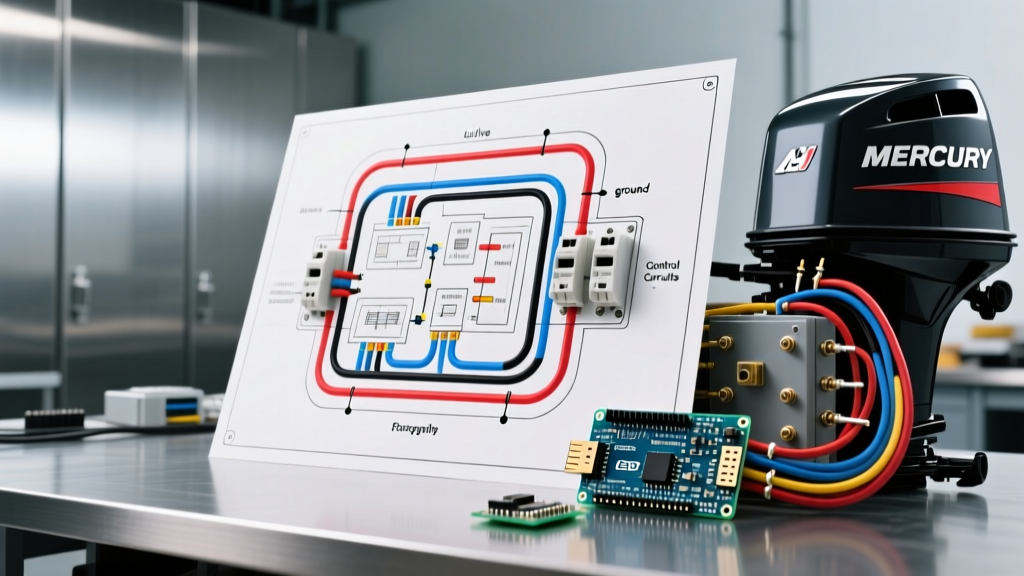
Integrating a modern outboard engine with a vessel's DC distribution network requires more than just plugging in a harness. When marine electricians and advanced DIYers consult a wiring diagram for Mercury outboard motor systems, the primary focus is often on the engine's internal ignition or fuel injection mapping. However, from a panel and breaker perspective, the critical task is safely routing high-amperage charging outputs, managing ignition loads, and protecting sensitive NMEA 2000 digital networks through the helm's main breaker panel.
In 2026, with the widespread adoption of digital switching systems like Mercury's VesselView and high-output alternators on models such as the Verado 300XL (producing up to 70 amps of charging current), the margin for error in wire gauge selection and breaker sizing has vanished. Undersized wires or improperly rated breakers can lead to catastrophic voltage drops, melted harnesses, or electrical fires. This guide decodes the panel-side integration of Mercury outboards, ensuring your DC distribution meets rigorous marine safety standards.
⚠️ ABYC E-11 Compliance Warning
All marine DC electrical installations in the United States should adhere to the American Boat & Yacht Council (ABYC) E-11 standards. Breakers must be sized to protect the wire, not the load. Never bypass a main battery disconnect or use automotive-grade fuses in a marine environment where ignition protection is required.
Core Components in a Mercury Outboard Electrical System
Before tracing the wiring diagram from the engine to the helm, you must identify the primary distribution hardware. A robust marine electrical panel setup for a Mercury-powered vessel typically includes:
- Main Battery Disconnect Switch: A heavy-duty, ignition-protected switch (e.g., Blue Sea Systems 9001e e-Series, rated for 300A continuous) capable of handling the engine's cranking amperage, which can exceed 250 amps on V8 outboards.
- Helm DC Breaker Panel: A waterproof or drip-proof panel (such as the Blue Sea ST Series, retailing between $180 and $280 in 2026) featuring magnetic hydraulic circuit breakers that trip based on thermal and magnetic thresholds, unaffected by the ambient temperature of an enclosed helm.
- Automatic Charging Relay (ACR) or DC-DC Charger: Essential for managing the alternator's output to both the starting and house battery banks without manual switching.
- Tinned Copper Busbars: Used to consolidate multiple ground and positive connections, eliminating the dangerous practice of stacking ring terminals on a single battery post.
Decoding the Wiring Diagram for Mercury Outboard Motor Connections
When you pull the official Mercury Marine service documentation for your specific engine serial number, the harness pinout is your roadmap. Here is how the critical circuits translate to your breaker panel.
1. The Main Battery and Cranking Circuit
The heaviest gauge wire in the system runs directly from the positive battery terminal, through the main disconnect switch, to the engine's main power stud (usually a red 2/0 AWG or 1/0 AWG cable). This circuit does not pass through the helm breaker panel. However, it must be protected by a Class T fuse or ANL fuse within 7 inches of the battery positive terminal. For a Mercury 150 FourStroke, a 150A ANL fuse paired with 1/0 AWG Ancor tinned marine wire is the standard configuration for runs up to 15 feet.
2. The Ignition and Kill Switch Circuit
The ignition circuit is routed through the helm breaker panel. On a standard Mercury 10-pin or 14-pin harness connector:
- Purple Wire (Ignition/Run): This wire carries 12V from the ignition switch to the engine's ECU. It should be protected by a 10A or 15A thermal magnetic breaker on the helm panel.
- Black/Yellow Wire (Kill/Ground): This is the emergency stop circuit. When the lanyard is pulled or the key is turned to 'Off', this wire is grounded, killing the ignition coils. It does not require a breaker but must be routed away from high-current positive cables to prevent induced voltage faults.
3. Alternator and Charging Output Routing
Modern Mercury outboards feature sophisticated voltage regulators. The charging output (often a thick red wire with an inline fuse near the engine block) must be routed to the house battery bank via an ACR. If you are routing this through a distribution busbar near the breaker panel, ensure the busbar is rated for at least 250A. Never route the raw alternator output through a standard 30A helm breaker; it will instantly trip or melt.
Breaker and Fuse Sizing Matrix for Mercury Integrations
Use the following matrix to select the correct marine circuit protection based on the specific circuit originating from or terminating at your Mercury outboard.
| Circuit Application | Wire Gauge (AWG) | Protection Device | Amp Rating |
|---|---|---|---|
| Main Engine Cranking Power | 1/0 or 2/0 | Class T / ANL Fuse | 150A - 250A |
| Ignition / ECU Power (Purple) | 10 AWG | Panel Breaker | 10A - 15A |
| Instrumentation / Gauges | 14 AWG | Panel Breaker | 5A - 10A |
| NMEA 2000 Network Power | 16 AWG | Inline Fuse / Panel | 3A - 5A |
| Alternator to ACR/Busbar | 6 AWG or 4 AWG | MRBF / ANL Fuse | 80A - 100A |
Step-by-Step: Routing Power from the Battery to the Helm Panel
To ensure clean power delivery to your ignition switch and digital gauges, follow this sequential routing protocol:
- Establish the Primary Busbars: Mount a positive and negative busbar (rated for 600V, 250A minimum) within 18 inches of the main battery switch. This acts as the central distribution hub.
- Feed the Helm Panel: Run a dedicated 6 AWG duplex marine cable from the primary busbars to the helm breaker panel. Protect the positive feed at the busbar with a 40A ANL fuse. This ensures the panel itself is protected before the individual branch breakers.
- Connect the Ignition Switch: Wire the 'B' (Battery) terminal on the back of the helm ignition switch to a 15A breaker on the panel. Wire the 'I' (Ignition) terminal to the purple wire in the Mercury main harness.
- Integrate the Kill Lanyard: The kill switch interrupts the black/yellow wire. Wire one side of the lanyard switch to the black/yellow harness wire, and the other side to a clean, dedicated ground busbar. Never ground the kill switch directly to the steering column or metal dash.
- Terminate with Heat Shrink: Every connection must use adhesive-lined marine heat shrink terminals. In 2026, the cost of 3M or Ancor heat shrink terminals (approx. $0.40 to $0.80 per piece) is negligible compared to the cost of diagnosing a saltwater-induced voltage drop.
Common Failure Modes and Troubleshooting
Even with a perfect wiring diagram, physical installation errors cause 90% of marine electrical failures. Watch for these specific edge cases:
Voltage Drop During Cranking
Symptom: The Mercury ECU throws a 'Low System Voltage' fault on the VesselView display, and the helm breaker panel lights dim significantly when the key is turned to 'Start'.
Diagnosis: The main 1/0 AWG cable is too long, or the connections at the battery switch are corroded. According to ABYC standards, voltage drop on a starting circuit should not exceed 10%. Use a digital multimeter to measure the voltage drop across the main switch while cranking. A drop greater than 0.3V indicates a failing switch or poor crimp.
Ground Loops in Digital Networks
Symptom: NMEA 2000 gauges flicker, or the engine drops out of 'SmartCraft' digital communication mode intermittently.
Diagnosis: The engine ground and the helm panel ground are taking different paths back to the battery, creating a ground loop. Ensure that the negative busbar at the helm is tied back to the main negative battery busbar with a wire gauge equal to the positive feed (e.g., 6 AWG). Do not rely on the boat's aluminum hull or steering cables as a ground path.
Thermal Breaker Nuisance Tripping
Symptom: The ignition breaker trips after 10 minutes of running in direct sunlight.
Diagnosis: Standard thermal breakers are highly sensitive to ambient heat. If your breaker panel is mounted in an unventilated, sun-baked center console, upgrade to magnetic hydraulic breakers (like the White Series from Blue Sea). These use a fluid-filled dashpot to delay thermal tripping, responding only to actual overcurrent events rather than ambient solar heat.
Expert References and Final Safety Checks
Working with high-output marine charging systems requires adherence to established safety protocols. Always consult the U.S. Coast Guard Boating Safety Division guidelines for federal requirements regarding battery ventilation and overcurrent protection. Furthermore, verify that all circuit breakers installed within 7 feet of the battery are ignition-protected (SAE J1171 / ISO 8846) to prevent the ignition of stray hydrogen gas emitted by lead-acid starting batteries.
By treating the wiring diagram for your Mercury outboard motor not just as an engine schematic, but as a blueprint for your vessel's entire DC distribution network, you ensure reliable starts, protected electronics, and ultimate safety on the water.