
Mastering the Wiring Diagram for Carrier Air Conditioner Systems
Reading a wiring diagram for Carrier air conditioner units requires more than just tracing lines from the contactor to the compressor. Whether you are servicing a legacy Comfort series, a mid-tier Performance model, or the advanced Infinity Greenspeed intelligence system, understanding the precise intersection of wire gauge sizing and color-coded standards is critical. Misinterpreting a schematic or undersizing a conductor doesn't just trip breakers; it degrades compressor lifespan, causes communication bus failures, and violates NFPA 70 (National Electrical Code) Article 440, which specifically governs air-conditioning and refrigerating equipment.
This guide breaks down the exact wire gauges, thermostat color codes, and communication bus requirements you need to safely and effectively wire Carrier HVAC systems in 2026.
Decoding the Carrier Thermostat Color Code Standard
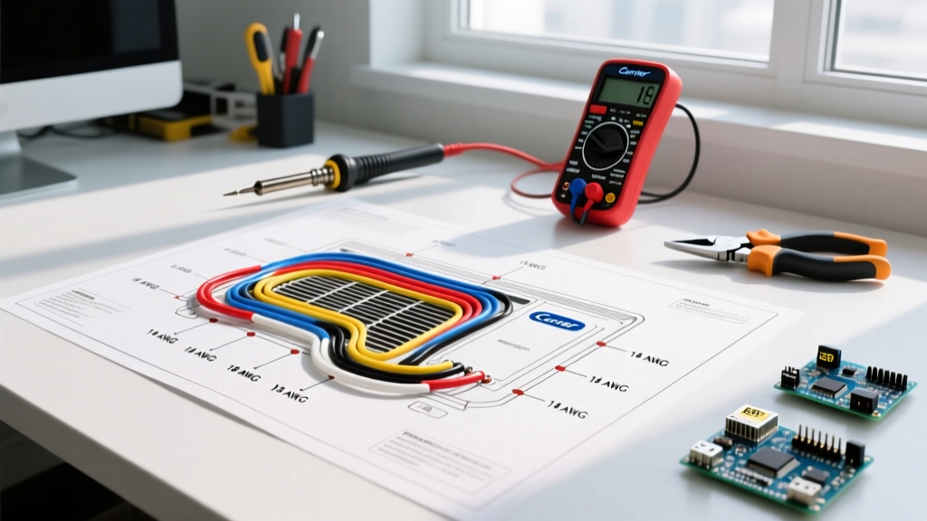
For standard Carrier split systems (like the Performance 16 SEER2 series), the low-voltage control wiring relies on the industry-standard 18 AWG solid-core thermostat cable. While Carrier schematics label terminals by letter rather than color, field technicians universally rely on the following color-to-terminal mapping to ensure the control board correctly triggers the contactor and blower.
| Wire Color | Carrier Terminal | Function & Schematic Path | Gauge Requirement |
|---|---|---|---|
| Red | R / Rc / Rh | 24VAC Hot (Power from transformer to thermostat) | 18 AWG Solid |
| Yellow | Y / Y1 | First Stage Cooling (Signals condenser contactor coil) | 18 AWG Solid |
| Green | G | Indoor Blower Fan (Energizes fan relay on control board) | 18 AWG Solid |
| White | W / W1 | First Stage Heat (Signals gas valve or heat strip relay) | 18 AWG Solid |
| Blue / Black | C | 24VAC Common (Completes circuit for smart thermostats) | 18 AWG Solid |
Pro Tip: If you are retrofitting an older Carrier WeatherExpert or early 2000s Comfort unit that lacks a dedicated 'C' wire, you must run a new 18/5 or 18/8 cable. Attempting to use the ground wire as a common return will cause severe electrical noise and potentially destroy the control board's 3-amp fuse.
High-Voltage Condenser Wiring: Matching Gauge to MCA
The most critical data on any Carrier condenser wiring diagram is the Minimum Circuit Ampacity (MCA) and Maximum Overcurrent Protection (MOCP) listed on the unit's data plate. According to the U.S. Department of Energy Central AC Guidelines and NEC Article 440.4, branch circuit conductors must be sized at 125% of the compressor and fan motor rated load amps.
Below is a reference matrix for common 2026 Carrier residential condensers (using 60°C ampacity ratings for standard NM-B Romex cable):
| Carrier Model Series | Unit Tonnage | MCA (Amps) | MOCP (Breaker) | Required Copper Wire Gauge |
|---|---|---|---|---|
| Comfort 24ACC6 (Single Stage) | 1.5 Ton | 9.5A | 15A | 14 AWG (or 12 AWG) |
| Performance 24SPA5 (Two-Stage) | 3.0 Ton | 18.2A | 25A | 12 AWG (Minimum) |
| Performance 24SPA5 (Two-Stage) | 4.0 Ton | 23.8A | 30A | 10 AWG (Minimum) |
| Infinity 20VNA8 (Greenspeed) | 5.0 Ton | 32.5A | 40A | 8 AWG (Minimum) |
The THHN vs. NM-B Ampacity Edge Case
Many journeyman electricians make a costly error when transitioning from indoor NM-B (Romex) to outdoor THHN in liquid-tight flexible metal conduit. If your run to a 3-ton Carrier condenser requires 12 AWG NM-B indoors, you can step down to 14 AWG THHN for the short outdoor whip only if the 75°C ampacity column is utilized and the termination lugs on the contactor are rated for 75°C. However, to maintain a uniform, fail-safe installation that passes strict municipal inspections, maintaining 12 AWG THHN throughout the whip is the industry best practice.
The Carrier Infinity Communicating System (A/B Bus)
If your wiring diagram for Carrier air conditioner components includes the Infinity System Control, throw away the standard color code chart. Infinity systems do not use 24VAC analog signals. Instead, they use a multiplexed digital communication bus operating over two wires, typically labeled A and B (or 1 and 2 on newer 2025/2026 control boards).
- Wire Type: 18 AWG stranded, 2-conductor, shielded cable.
- Polarity: The A/B bus is non-polarized at the physical layer, meaning swapping A and B will not damage the board, but it can introduce latency in older firmware versions.
- Shielding Requirement: The shield must be grounded at the indoor air handler control board only. Grounding both ends creates a ground loop, which introduces 60Hz hum and causes the Infinity system to throw 'System Malfunction' communication errors (Code 81 or 82).
CRITICAL SAFETY WARNING: Before tracing any wiring diagram or testing continuity on a Carrier control board, you must execute proper Lockout/Tagout (LOTO) procedures. According to OSHA Electrical Safety Standards, simply turning off the thermostat does not de-energize the board. You must disconnect the high-voltage disconnect box outside and trip the indoor air handler breaker, verifying zero voltage with a CAT III or CAT IV multimeter before touching any terminals.
Step-by-Step Verification Using the Condenser Schematic
Every Carrier condenser features a laminated wiring diagram glued to the inside of the access panel. Here is how to systematically verify your wiring against it:
- Locate the Power Entry: Find L1 and L2 on the schematic. Trace them to the contactor's line-side terminals. Ensure your high-voltage ground (bare copper or green) is bonded to the chassis ground lug, not the neutral bar.
- Verify the Contactor Coil Voltage: Look at the coil symbol on the diagram. Older Carrier units might use a 120V or 240V coil, but almost all modern Carrier units (post-2015) use a 24VAC coil. Trace the 24V wires back to the Y and C terminals on the terminal block.
- Check the High-Pressure Switch: Modern Carrier diagrams show the high-pressure switch wired in series with the contactor coil. If the system isn't pulling in the contactor, use your multimeter to check for continuity across this switch. If it's open, the system has tripped on high head pressure.
- Inspect the Dual Capacitor Wiring: The diagram will show 'HERM' (Hermetic/Compressor), 'FAN' (Condenser Fan), and 'C' (Common). Ensure the compressor start winding is on HERM and the fan is on FAN. Reversing these will result in the fan motor running backward or the compressor failing to start, eventually tripping the internal thermal overload.
Frequently Asked Questions
Can I use 14/2 Romex for a 3-ton Carrier AC if the MCA is 19.8A?
No. NEC 240.4(D) strictly limits 14 AWG copper to a maximum overcurrent protection of 15 Amps for residential branch circuits, regardless of the HVAC exception rules. If the MCA is 19.8A, you must use a 20A or 25A breaker, which mandates a minimum of 12 AWG copper wire.
What happens if I use unshielded thermostat wire for a Carrier Infinity A/B bus?
Unshielded wire acts as an antenna. If the low-voltage wire is routed parallel to the 240V high-voltage whip inside the wall cavity, electromagnetic interference (EMI) will corrupt the digital packets. The Infinity control will interpret this as a dropped device, resulting in intermittent system shutdowns and 'Lost Communication' fault codes.
Why does my Carrier wiring diagram show a 'D' terminal?
On Carrier heat pump models, the 'D' terminal is often used for the defrost board or auxiliary heat staging. Always cross-reference the specific model number's service manual, as terminal designations can shift between the Comfort, Performance, and Infinity series.