
The Regulatory Framework: Why Code Compliance is Non-Negotiable
When towing a 10,000 lb fifth-wheel RV or a commercial flatbed, a standard wiring diagram for 7 pin trailer lights is not merely a suggestion—it is a strict legal and safety requirement. In 2026, with the widespread adoption of advanced PWM (Pulse Width Modulation) brake controllers and all-LED trailer lighting, the electrical demands and failure modes of trailer wiring have evolved significantly. Non-compliant wiring doesn't just result in blown fuses; it causes voltage drops that violate Federal Motor Vehicle Safety Standard (FMVSS) 108 candela minimums, leading to catastrophic rear-end collisions and severe liability in the event of an accident.
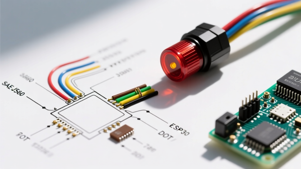
To ensure absolute safety, your wiring diagram for 7 pin trailer lights must adhere to two primary frameworks: the FMVSS 108 lighting regulations enforced by the NHTSA, and the connector and wiring standards established by SAE International (specifically SAE J560 for commercial and RVIA adaptations for recreational vehicles). This guide provides the exact specifications, wire gauges, and circuit protection protocols required to build a safe, code-compliant 7-way trailer harness.
The SAE J560 vs. RVIA 7-Pin Wiring Matrix
One of the most dangerous pitfalls in trailer wiring is confusing the Commercial SAE J560 standard with the Recreational RVIA/Bargman standard. While both use a 7-pin round connector, the color codes and pin assignments for auxiliary power and ABS/brakes differ drastically. Cross-wiring these can send 12V continuous power directly into your trailer's electric brake magnets, causing them to overheat and seize while driving.
| Pin | Function | RVIA / RV Standard Color | SAE J560 Commercial Color | Minimum Wire Gauge |
|---|---|---|---|---|
| 1 | System Ground | White | White | 10 AWG or 8 AWG |
| 2 | Electric Brakes | Blue | Black (ABS Power) | 10 AWG |
| 3 | Tail / Running Lights | Brown | Brown | 12 AWG |
| 4 | 12V Auxiliary / Battery Charge | Black (or Red) | Red (12V Aux) | 10 AWG or 8 AWG |
| 5 | Right Turn / Stop | Green | Green | 12 AWG |
| 6 | Left Turn / Stop | Yellow | Yellow | 12 AWG |
| 7 | Reverse / Aux | Purple | Blue (Brakes) | 12 AWG |
Critical Safety Warning: Never assume wire colors match the connector pins. Always use a digital multimeter to verify pinout functions at the tow vehicle's receptacle before splicing into the trailer harness. According to SAE International J560 guidelines, physical pin location dictates function, not insulation color.
Wire Insulation Standards: Beyond Standard PVC
A common failure mode in DIY trailer wiring is the use of standard THHN or TW PVC-insulated wire. PVC becomes brittle in sub-zero temperatures and melts or shorts when routed near exhaust components or axle heat. For a code-compliant wiring diagram for 7 pin trailer lights, you must use cross-linked polyethylene (XLPE) insulated wire meeting SAE J1128 specifications.
- GXL (General Cross-Linked): Standard wall thickness. Excellent for general trailer routing.
- SXL (Special Cross-Linked): Thinner wall, higher heat resistance. Ideal for tight conduit runs.
- TXL (Thin Cross-Linked): Ultra-thin. Best for weight-sensitive applications, but requires split-loom protection to prevent abrasion.
For the main 7-way trunk cable, purchase a bonded, jacketed multi-conductor cable (often sold as 7-way flat or round bonded cable) that features an outer PVC jacket for UV and abrasion resistance, housing individually colored GXL wires inside.
Voltage Drop and Wire Gauge Selection
The NEC and SAE both emphasize mitigating voltage drop, which is especially critical on modern 5th-wheel trailers that can exceed 45 feet in total wire run length from the tow vehicle alternator to the trailer's rear marker lights. If voltage drops below 10.5V at the trailer brakes, the PWM brake controller cannot deliver full stopping torque.
Calculating the 12V Auxiliary Run (Pin 4)
Pin 4 is frequently used to charge trailer breakaway batteries or power interior 12V appliances. A standard 12 AWG wire has a resistance of roughly 1.58 ohms per 1,000 feet. Over a 50-foot round trip (100 feet total), drawing 15A for a trailer fridge or battery charger results in a voltage drop of over 2.3V. This leaves only 11.7V at the trailer, which is insufficient for proper battery charging.
The Code-Compliant Fix: Upgrade Pin 4 and Pin 1 (Ground) to 10 AWG or 8 AWG SXL wire. This reduces the voltage drop to under 1.0V, ensuring safe and efficient power transfer.
Overcurrent Protection: Fuses and Auto-Reset Breakers
A compliant wiring diagram for 7 pin trailer lights must include localized overcurrent protection at the tow vehicle's distribution point. Relying solely on the vehicle's internal cabin fuses is a severe fire hazard, as the wire run from the cabin to the rear bumper is long and susceptible to chafing.
For the high-amperage circuits (Pin 2: Brakes and Pin 4: 12V Aux), you must install Type 1 Auto-Reset Circuit Breakers (e.g., Bussmann 181-Series or Littelfuse MEGA/ANL fuses for static loads). Type 1 breakers cycle on and off when overloaded, which is a dangerous failure mode for electric brakes. Therefore, for the brake circuit (Pin 2), a 30A or 40A manual-reset PRV (Push-Reset-Verify) breaker or a fuse block is heavily preferred by safety inspectors, as it forces the driver to acknowledge and investigate a short circuit rather than blindly continuing to drive with cycling brakes.
- Mount the circuit breakers within 18 inches of the tow vehicle's battery positive terminal.
- Use copper ring terminals with heat-shrink adhesive lining (dual-wall polyolefin) to prevent moisture intrusion and galvanic corrosion.
- Secure all wiring with UV-resistant nylon cable ties every 12 inches, avoiding zip-ties directly over sharp metal edges without a rubber grommet.
The Grounding Imperative: Eliminating the Floating Ground
Over 70% of all trailer lighting anomalies—such as dimming brake lights when the turn signal is engaged—are caused by inadequate grounding. In a 7-pin system, Pin 1 (White) is the dedicated ground return. However, relying solely on the trailer hitch ball for grounding is a massive safety violation.
The white ground wire must be terminated using a star washer and a self-tapping sheet metal screw or bolted directly to bare, unpainted steel on the trailer's main chassis tongue. The ground wire gauge must equal or exceed the largest power wire in the harness (typically 10 AWG). Furthermore, every individual LED trailer light must have its own localized ground wire bonded to the trailer frame, creating a redundant ground mesh that prevents 'backfeed' through the running light circuit.
Modern Edge Cases: LEDs and PWM Controllers
As of 2026, nearly all new trailers utilize LED lighting. While LEDs draw significantly less current (often 0.2A per lamp compared to 2.1A for incandescent bulbs), this creates a new compliance issue: hyperflashing. Tow vehicle BCMs (Body Control Modules) monitor circuit resistance to detect blown bulbs. The low draw of LEDs tricks the BCM into thinking a bulb is out, causing rapid flashing.
Do not use cheap, heat-generating load resistors spliced into the wiring harness, as these can reach 300°F and melt adjacent wiring, violating fire safety codes. Instead, install a solid-state CANbus-compatible LED flasher relay or use a tow-module bypass harness (like the Tekonsha Plug-In Vehicle Wiring Harness) that interfaces directly with the vehicle's CANbus system, bypassing the bulb-out detection logic safely.
Additionally, modern PWM brake controllers (like the Curt Spectrum or Redarc Tow-Pro) send rapid pulses to the trailer brakes. If your wiring diagram utilizes undersized wire or poor butt-splice connectors, the high-frequency pulses will cause arcing and rapid connector degradation. Always use nylon-insulated crimp connectors with a ratcheting crimp tool (e.g., Titan 11939) to ensure a gas-tight mechanical bond that can withstand PWM electrical stress.
Final Safety & Compliance Checklist
- Verify pinout with a multimeter before splicing; do not trust wire colors blindly.
- Confirm all wire is SAE J1128 GXL or SXL cross-linked insulation.
- Ensure Pin 1, Pin 2, and Pin 4 are upgraded to 10 AWG for long-distance runs.
- Install manual-reset breakers or fuses within 18 inches of the tow vehicle battery.
- Terminate all grounds to bare metal using star washers; never ground to painted surfaces or aluminum brackets.
- Seal all exterior connections with dielectric grease (e.g., Permatex 22058) to prevent oxidation.
By strictly adhering to this code-compliant wiring diagram for 7 pin trailer lights, you ensure your rig meets all federal and industry safety standards, protecting both your equipment and the motorists sharing the road with you. For further reading on commercial lighting requirements, consult the NHTSA Lighting and Reflective Devices guidelines.