
Mastering the Wiring Diagram for Carrier Heat Pump Systems
Interpreting a wiring diagram for Carrier heat pump systems requires a solid grasp of both high-voltage power distribution and low-voltage communicating protocols. Whether you are servicing a legacy Performance series unit or a cutting-edge Carrier Infinity 20VS (25VNA0) heat pump, the schematic is your primary diagnostic tool. Misreading these diagrams is the leading cause of blown control boards, tripped breakers, and premature motor failure. In this motor wiring tutorial, we break down the exact terminal mappings, ECM communication buses, and 2026 NEC compliance standards required for safe, accurate installations.
Safety Warning: Before opening any condenser or air handler panel, execute a strict Lockout/Tagout (LOTO) procedure. Verify zero energy using a CAT III or CAT IV multimeter (such as the Fluke 116 HVAC Multimeter) across L1, L2, and Ground. Capacitors in Carrier units can hold lethal charges exceeding 400VDC long after power is disconnected.
Decoding Carrier Schematic Conventions
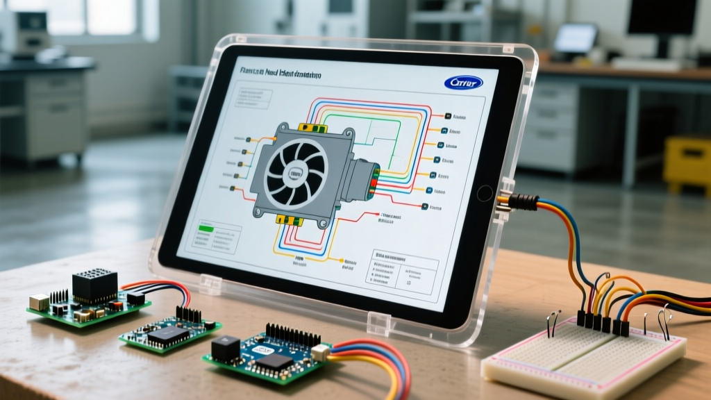
Carrier typically provides two types of diagrams on the inside of the condenser access panel: the Ladder Diagram (line format) and the Pictorial Diagram. For motor wiring, the pictorial diagram is generally more useful for physical routing, while the ladder diagram is essential for tracing logical control sequences through the contactor, defrost board, and pressure switches.
Standard Color Codes in Carrier Heat Pumps
- Black / Red: 240V Line Voltage (L1 / L2)
- White: 240V Line Voltage (L2 - alternate routing) or 120V Neutral
- Yellow / Blue: 24V Low Voltage (Y, C, W, O/B)
- Brown / Brown-White: PSC Condenser Fan Motor Capacitor Leads
- Green / Bare Copper: Equipment Grounding Conductor (EGC)
Wiring the PSC Condenser Fan Motor (HC39AE Series)
Many Carrier Performance and WeatherExpert heat pumps utilize a Permanent Split Capacitor (PSC) motor for the outdoor condenser fan. A common OEM replacement is the HC39AE1153 (1/4 HP, 825 RPM, 208/230V, 1.5 Amps). In 2026, an OEM HC39AE motor typically costs between $180 and $240, while universal aftermarket equivalents range from $90 to $130.
Step-by-Step PSC Motor Wiring
- Identify the Leads: The HC39AE features three primary wires: Black (Line), Brown (Start/Capacitor), and Brown with a White Stripe (Common/Capacitor).
- Wire the Capacitor: Connect the Brown wire to the 'F' (Fan) terminal on the dual run capacitor (e.g., a 45/5 MFD 370V capacitor). Connect the Brown/White wire to the 'C' (Common) terminal on the capacitor.
- Wire the Contactor: Connect the Black wire to the T1 load terminal on the main contactor. The T2 terminal of the contactor will also have a jumper wire connecting to the 'C' terminal on the capacitor to complete the 240V circuit.
| Motor Wire Color | Destination | Function |
|---|---|---|
| Black | Contactor T1 | Main 240V Line Power (Switched) |
| Brown | Capacitor 'F' (Fan) | Start Winding Phase Shift |
| Brown / White Stripe | Capacitor 'C' (Common) | Run Winding Return Path |
Expert Troubleshooting Tip: A common DIY mistake is attempting to reverse the rotation of a PSC fan motor by swapping L1 and L2 at the contactor. This will not work. PSC motor rotation is dictated by the internal winding geometry. If you buy a CW (Clockwise) motor and your Carrier unit requires CCW (Counter-Clockwise), the motor will push air out the top instead of pulling it through the coil. You must replace it with the correct rotation model.
Tackling the Carrier Infinity ECM Blower Motor
Indoor air handlers paired with Carrier Infinity heat pumps (like the 25HNB7) use advanced Electronically Commutated Motors (ECMs). These are not simple AC induction motors; they are essentially three-phase DC motors with integrated microprocessors. The Carrier Infinity system relies on a proprietary RS-485 communicating bus rather than standard 24V thermostat wires.
The 4-Wire Communicating Bus
When reading the wiring diagram for Carrier heat pump air handler control boards, you will notice a 4-pin terminal block labeled A, B, C, and D (or sometimes 24V, C, Data+, Data-).
- Terminal A (24VAC): Provides continuous 24V power to the motor's internal logic board.
- Terminal B (Common): The 24VAC return path.
- Terminal C (Data +): RS-485 positive data transmission.
- Terminal D (Data -): RS-485 negative data transmission.
The high-voltage section of the ECM requires 240V (L1/L2) or 120V (L1/N) depending on the tonnage of the air handler. This is fed through a 16-pin Molex connector or a direct screw-terminal block on the motor module. Never apply 240V to the A/B/C/D communicating terminals; doing so will instantly destroy the motor module and the Infinity System Control wall thermostat, resulting in a repair bill exceeding $1,200.
Troubleshooting Matrix: Carrier Motor Fault Codes
Modern Carrier heat pumps feature onboard LED diagnostics or Infinity wall control fault codes. Cross-reference these codes with your wiring diagram to isolate motor circuit failures.
| Fault Code | System State | Diagnostic Action & Electrical Test |
|---|---|---|
| Code 13 | High Pressure Switch Open | Condenser fan may have failed. Check 240V at contactor T1/T2. Verify fan capacitor MFD rating with a multimeter. |
| Code 41 | Communicating Bus Error | Check continuity on A/B/C/D wires. Ensure no 120V/240V cross-overs. Measure 24VAC between A and B at the motor module. |
| Code 44 | Blower Motor Fault | ECM module failure or thermal overload. Disconnect 16-pin plug, check for burnt pins. Measure stator winding resistance (should be balanced across all 3 phases). |
| Code 81 | Outdoor Unit Comm Loss | Verify 24V low voltage wire (Yellow/Blue) from indoor board to outdoor defrost control board. Check for chewed thermostat wires. |
NEC Compliance & 2026 Installation Standards
When installing or replacing motors based on a Carrier schematic, technicians must adhere to the latest National Electrical Code (NEC) standards. According to NFPA 70 (National Electrical Code), Article 440 governs Air-Conditioning and Refrigerating Equipment.
GFCI Protection for Outdoor Disconnects
One of the most significant updates impacting HVAC wiring in recent code cycles (and strictly enforced in 2026) is the requirement for Ground Fault Circuit Interrupter (GFCI) protection for outdoor HVAC receptacles and specific disconnect setups. While hardwired 240V condenser units generally do not require GFCI breakers under standard Article 440, any 120V service receptacle mounted on or within 25 feet of the condenser pad must be GFCI protected. Furthermore, if your local jurisdiction has adopted AFCI/GFCI combination requirements for 240V HVAC circuits to prevent arc faults in aging motor windings, you must install a specialized HVAC-rated GFCI breaker to prevent nuisance tripping during compressor startup.
Wire Sizing and Voltage Drop
The U.S. Department of Energy emphasizes that improper wire sizing leads to voltage drop, which severely degrades heat pump efficiency and destroys ECM modules. For a standard 3-ton Carrier heat pump drawing a maximum of 30 amps (RLA), you must use a minimum of 10 AWG copper THHN wire for runs up to 50 feet. If the run from the main panel to the outdoor disconnect exceeds 75 feet, you must step up to 8 AWG copper to maintain a voltage drop below 3%, ensuring the ECM inverter receives clean, stable voltage.
Final Takeaways for HVAC Technicians and DIYers
Successfully navigating a wiring diagram for Carrier heat pump units bridges the gap between mechanical repair and digital diagnostics. Always verify the exact model number on the condenser data plate—Carrier frequently updates control board revisions mid-production run, meaning a 2024 schematic might differ slightly from a 2026 revision of the same model series. Invest in a high-quality capacitance meter, respect the RS-485 communicating bus limitations, and always prioritize NEC-compliant grounding and disconnect practices. For further efficiency standards and equipment certifications, refer to the ENERGY STAR Heat Pump Specifications to ensure your wired system meets modern SEER2 and HSPF2 benchmarks.