
The Critical Role of Circuit Protection in Trailer Braking
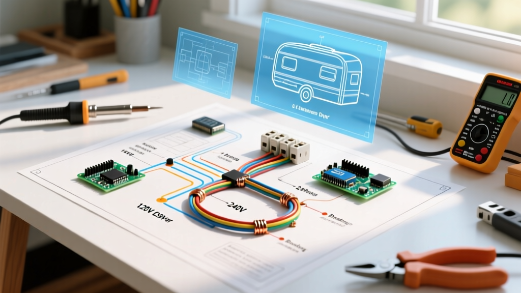
When engineering a safe towing setup, the electric trailer brakes wiring diagram is often oversimplified by generic guides that ignore the critical role of circuit protection and voltage management. Electric trailer brakes are not passive components; under heavy braking or a breakaway scenario, a tandem-axle trailer can draw upwards of 25 to 30 amps continuously. If your tow vehicle's breaker panel and wire gauges are not correctly sized, you risk voltage drop, melted 7-way connectors, or catastrophic brake failure on steep descents.
From a panel and breaker integration perspective, routing power from the alternator to the brake controller and out to the trailer requires adherence to strict automotive electrical standards. According to the Federal Motor Carrier Safety Administration (FMCSA), every wheel on a commercial trailer over a certain weight threshold must have functional brakes, making the reliability of your DC circuit paramount. This guide breaks down the exact breaker sizing, wire gauge selection, and routing protocols required for a bulletproof 2026 towing setup.
Core Architecture: Battery, Breaker, and Controller
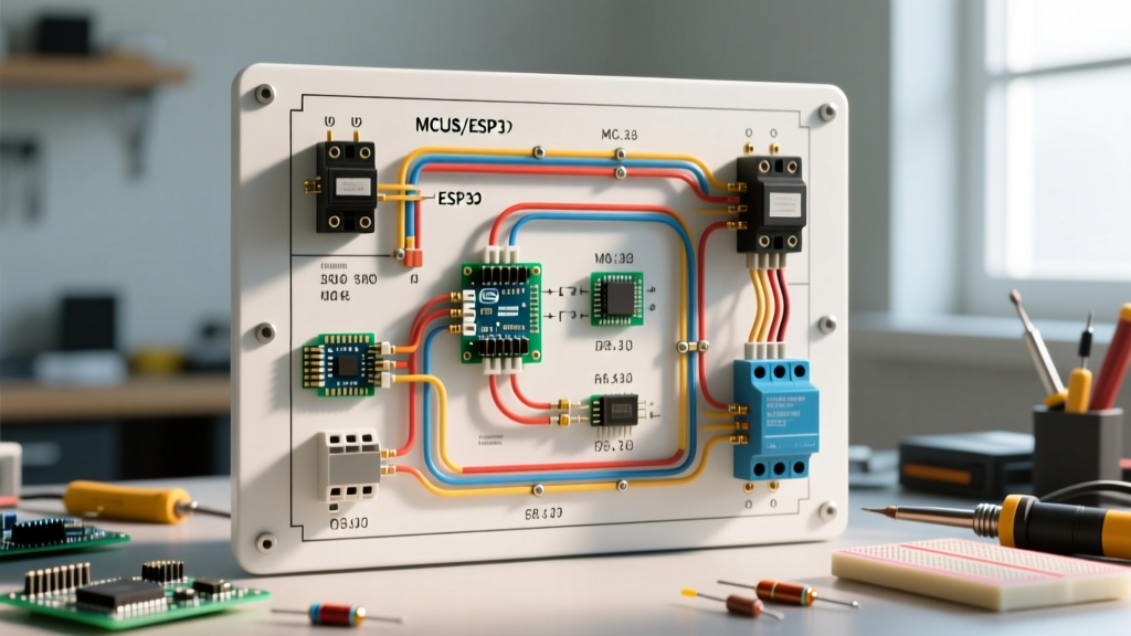
A properly engineered electric trailer brake circuit bypasses the vehicle's standard interior fuse panel for the main high-current feed. Instead, it draws directly from the battery or alternator stud, passing through a dedicated, high-amperage auto-resetting circuit breaker before entering the cabin to feed the brake controller.
Selecting the Right Auto-Resetting Circuit Breaker
For 12V DC automotive applications, you must use a Type 1 (Auto-Resetting) Thermal Circuit Breaker. Unlike standard blade fuses (ATC/ATO) which blow and require replacement, a thermal breaker utilizes a bimetallic strip that opens the circuit when overheated by an overcurrent event, then automatically resets once it cools. This is critical for trailer brakes: if a momentary short or surge trips the breaker on a mountain pass, the system will reset in seconds, restoring braking power without requiring you to stop and replace a fuse.
- Recommended Brands: Bussmann 18-Series, Littelfuse, or Cole Hersee.
- Mounting: Must be installed within 18 inches of the battery positive terminal to protect the entire length of the main feed wire.
- Cost: Typically $12 to $25 for a high-quality 40A unit.
Wire Gauge and Breaker Sizing Matrix
Selecting the correct wire gauge is dictated by the total amperage draw of your trailer's brake magnets and the physical length of the wire run. Standard PVC-insulated wire is insufficient for under-hood routing; you must use SAE J1128 compliant cross-linked polyethylene (XLPE) insulated wire, such as TXL or GXL, which withstands engine bay temperatures up to 125°C (257°F).
| Trailer Axle Count | Total Brake Magnets | Max Current Draw | Required Breaker Size | Minimum Wire Gauge (Under 20ft) | Minimum Wire Gauge (Over 20ft) |
|---|---|---|---|---|---|
| Single Axle | 2 | 10A - 12A | 20A or 30A | 12 AWG GXL | 10 AWG GXL |
| Tandem Axle | 4 | 20A - 24A | 30A or 40A | 10 AWG GXL | 8 AWG GXL |
| Triple Axle | 6 | 30A - 36A | 40A or 50A | 8 AWG GXL | 6 AWG GXL |
The Definitive Electric Trailer Brakes Wiring Diagram Path
To ensure zero ambiguity, here is the exact step-by-step routing path for the primary brake power circuit, utilizing a modern proportional controller like the Tekonsha Prodigy P3 ($165) or the Redarc Tow-Pro Elite ($215).
- Battery to Breaker: Run 10 AWG (or 8 AWG) red GXL wire from the battery positive terminal to the copper stud on the 40A auto-resetting breaker.
- Breaker to Firewall: From the breaker's output stud, route the red wire through the vehicle firewall using a sealed rubber grommet.
- Firewall to Controller: Connect the red wire to the Black wire on the brake controller's wiring pigtail (this is the 12V+ power input).
- Controller Ground: Connect the controller's White wire to a clean, bare-metal chassis ground near the dash. Do not daisy-chain this ground with other accessories.
- Controller to 7-Way (Brake Output): Route the controller's Blue wire (brake output) back through the firewall and down the frame rail to the rear 7-way connector.
- Controller to 7-Way (Stoplight Switch): Splice the controller's Red wire into the vehicle's dedicated stoplight switch circuit (usually found at the brake pedal arm or the BCM).
Voltage Drop Calculations: The Hidden Braking Killer
Many DIYers use 12 AWG wire for tandem-axle trailers to save money, ignoring voltage drop over long chassis runs. Electric brake magnets require a minimum of 11.5V to engage with full proportional force. If your alternator is outputting 13.8V, but you experience a 2.5V drop due to undersized wire and poor connections, your trailer brakes are only receiving 11.3V, resulting in a 15% to 20% loss in stopping power.
Expert Insight: When wiring a 25-foot run (50 feet total loop) for a 4-brake tandem axle drawing 24A, 12 AWG wire will yield a voltage drop of approximately 2.4V. Upgrading to 10 AWG reduces that drop to 1.5V, and 8 AWG drops it to a negligible 0.9V. Always oversize your wire by one gauge for runs exceeding 15 feet.
7-Way RV Blade Connector Integration
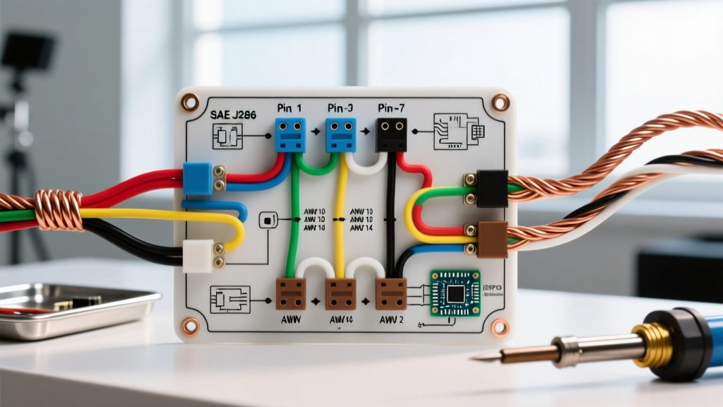
The 7-way connector is the most common failure point in any electric trailer brakes wiring diagram. The physical pins are exposed to moisture, road salt, and vibration. When integrating your blue brake output wire into the 7-way plug, adhere to the standard US RV pinout:
- Pin 1 (Bottom Left): Ground (White) - Must be 10 AWG or 8 AWG directly to the frame.
- Pin 2 (Lower Right): Tail/Running Lights (Brown)
- Pin 3 (Lower Left): Left Turn/Stop (Yellow)
- Pin 4 (Top Left): 12V Auxiliary Power (Black)
- Pin 5 (Bottom Right): Electric Brakes (Blue) - This is your primary brake controller output.
- Pin 6 (Top Right): Right Turn/Stop (Green)
- Pin 7 (Center): Reverse Lights/Aux (Purple)
Pro-Tip for 7-Way Reliability: Apply a thin layer of dielectric grease (like Permatex 22058) inside the 7-way socket to prevent galvanic corrosion between the brass pins and the trailer's plug. Corrosion increases resistance, which mimics a voltage drop and weakens braking performance.
Common Failure Modes and Edge Cases
Even with a perfect diagram, real-world conditions introduce edge cases. Here is how to troubleshoot the most common panel and breaker-related failures:
1. The 'Phantom' Tripped Breaker
If your 40A breaker trips intermittently without a hard short, check for inrush current. When brake magnets are cold, their resistance is slightly lower. If you are towing a heavy triple-axle trailer in freezing temperatures, the initial current spike when the controller engages can briefly exceed 45A, nuisance-tripping a standard thermal breaker. Solution: Upgrade to a 50A breaker and ensure your wire is 6 AWG, or install a magnetic-hydraulic breaker which handles inrush spikes better than purely thermal models.
2. Melted 7-Way Plugs
A melted 7-way plug is rarely caused by the brake circuit alone; it is usually the 12V Auxiliary pin (Pin 4) drawing continuous current for trailer interior lights or battery charging, combined with loose pin tension. Solution: If running a dedicated charge line to the trailer battery via Pin 4, use a separate 30A breaker and 10 AWG wire. Never route the charge line and the brake output through the same undersized ground path.
3. Controller 'S.H.' (Short) Error Codes
If your Tekonsha or Curt controller flashes a short circuit code, the issue is often not a bare wire touching the frame. It is frequently a failed brake magnet inside the trailer hub. When a magnet's internal windings melt and short, it drops the circuit resistance to near zero, instantly drawing maximum amperage and triggering the controller's internal protection. Use a multimeter to test resistance across the trailer's brake pins; a healthy magnet should read between 3.0 and 4.5 ohms.
Final Panel Integration Checklist
Before finalizing your tow vehicle's electrical panel, verify the following:
- All under-hood connections utilize adhesive-lined heat shrink ring terminals (not crimp-only vinyl terminals).
- The main breaker is mounted vertically to ensure the thermal bimetallic strip operates correctly via convection.
- The brake controller ground is sanded down to bare, unpainted steel and secured with a star washer.
- The blue brake output wire is wrapped in split-loom tubing and secured with UV-resistant zip ties every 12 inches to prevent chafing against the frame.
By treating your electric trailer brakes wiring diagram as a high-current industrial circuit rather than a simple automotive accessory, you ensure that your braking system responds instantly and reliably, regardless of the terrain or weather conditions.