
Understanding the Aprilaire 700 Electrical Architecture
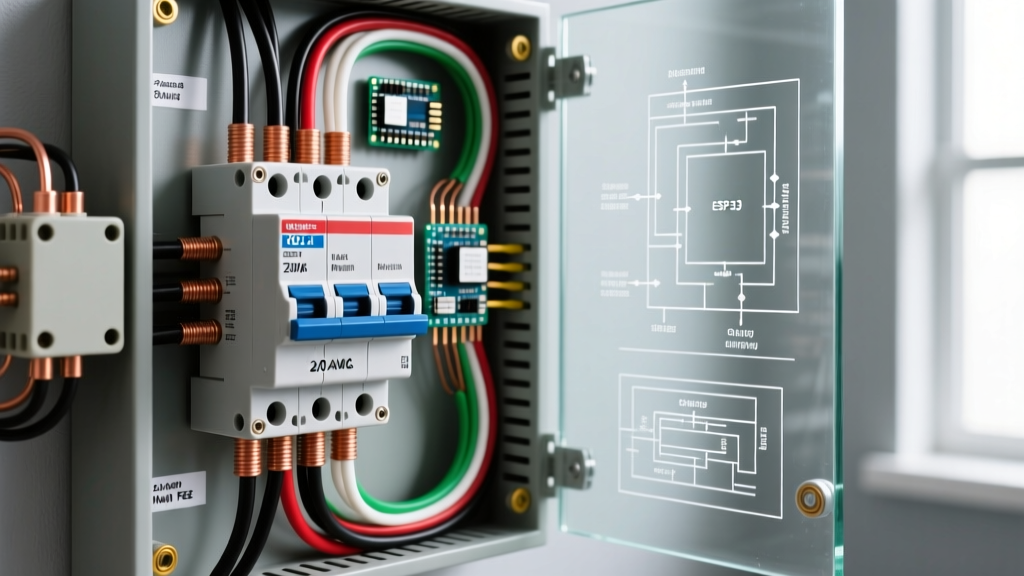
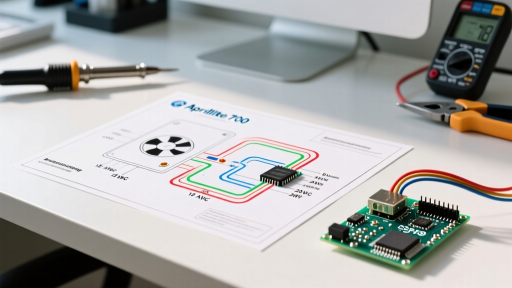
The Aprilaire 700 is a high-capacity, power-fan humidifier designed for homes up to 4,200 square feet. Unlike bypass models (such as the 600 series), the 700 series utilizes an integrated 120VAC fan motor to actively push moisture into the ductwork. This architectural difference fundamentally changes the wiring diagram for Aprilaire 700 installations, requiring two completely isolated electrical circuits: a 120VAC line-voltage circuit for the fan, and a 24VAC low-voltage circuit for the solenoid valve and humidistat control.
As of 2026, with the average cost of the Aprilaire 700 unit ranging between $290 and $340, improper wiring remains the leading cause of premature component failure. Misrouting line voltage into the 24V control board or humidistat will instantly destroy the components and pose a severe fire hazard. This reference guide provides the exact specifications, wire gauges, and diagnostic flows required for a code-compliant installation.
Component Specifications & Wire Gauge Matrix
Selecting the correct wire gauge is critical for both safety and National Electrical Code (NEC) compliance. The 120V circuit must be rated to match the breaker of the source junction box, while the 24V circuit falls under Class 2 wiring standards.
| Component | Voltage / Power | Amperage Draw | Required Wire Gauge | Connection Terminals |
|---|---|---|---|---|
| Fan Motor | 120VAC, 60Hz | ~0.8A | 14 AWG (Copper) | Line (Black), Neutral (White), Ground (Green) |
| Water Solenoid Valve (Part #35) | 24VAC | 0.5A Max | 18 AWG (Thermostat Wire) | Valve Terminals (No Polarity) |
| Humidistat / Digital Control | 24VAC | 0.1A | 18 AWG | R, C, H, G (Varies by Control Model) |
| Step-Down Transformer (If not using furnace board) | 120V to 24VAC | 40VA Rating | 14 AWG (Primary), 18 AWG (Secondary) | Primary: L1/L2, Secondary: 24V/C |
Step-by-Step Wiring Diagram Reference
1. The 120VAC Fan Motor Circuit
The most common error when interpreting the wiring diagram for Aprilaire 700 is attempting to power the fan from the 24V furnace transformer. The 700 series fan requires a dedicated 120VAC source.
- Source: Tap into a nearby 120V junction box or use a dedicated 15A/20A receptacle with an approved appliance cord kit.
- Hot (Black): Connect the 14 AWG black wire from the power source to the black fan lead.
- Neutral (White): Connect the 14 AWG white wire to the white fan lead.
- Ground (Green/Bare): Connect to the humidifier chassis ground screw and the source ground. Never leave the chassis ungrounded, as the metal casing can become energized if the solenoid leaks water onto the motor.
2. The 24VAC Solenoid & Control Circuit
The solenoid valve controls water flow to the evaporation pad. It requires 24VAC to open. You can source this 24VAC directly from the furnace control board (if it has dedicated 'H' and 'C' terminals) or via a dedicated 40VA transformer (Aprilaire Part #130-501).
- Run 18 AWG 2-conductor thermostat wire from the 24V source to the humidistat.
- Wire the humidistat in series with the solenoid. One side of the solenoid connects to the humidistat switch leg, and the other side returns to the 24V common (C).
- Use blue wire nuts (e.g., Ideal 341) for 18 AWG splices to ensure the copper strands do not fray and short against the chassis.
3. Blower Interlock Integration (Current Sensing)
The Aprilaire 700 should only operate when the HVAC blower is running to prevent ductwork saturation. If your furnace board lacks an 'H' terminal, you must use a current sensing relay like the Aprilaire 50.
- Clamp the Aprilaire 50 sensor around the hot lead of the furnace blower motor (not the common).
- Wire the relay contacts in series with the 24V humidistat circuit.
- Adjust the sensitivity dial on the relay until it clicks exactly when the blower engages.
Critical Failure Modes & Edge Cases
WARNING: The 120V/24V Cross-Wire Catastrophe
If a technician accidentally feeds 120V line voltage into the 24V solenoid or the digital humidistat, the components will violently fail, often melting the wire insulation and destroying the furnace control board. Always verify voltage with a multimeter before connecting low-voltage control wires. According to the National Electrical Code (NEC), Class 1 (line voltage) and Class 2 (low voltage) wiring must be separated by at least 1/4 inch or divided by a physical barrier inside the junction box.
Edge Case: Furnace Transformer Overload
Modern high-efficiency furnaces often have 40VA transformers that are already near capacity powering smart thermostats and advanced ECM motor boards. Adding a 0.5A solenoid draw can push the transformer past its limit, causing it to overheat and trip its internal thermal fuse. If your furnace board lacks a dedicated humidifier terminal, always install a separate 40VA transformer for the Aprilaire 700.
Multimeter Diagnostics & Expected Values
When troubleshooting a unit that fails to produce humidity, use these exact diagnostic thresholds:
- Solenoid Coil Resistance: Disconnect power and measure across the solenoid terminals. A healthy Aprilaire #35 solenoid will read between 35 and 45 ohms. A reading of OL (Open Line) indicates a burned-out internal coil requiring a $65 replacement.
- Control Voltage: With the furnace blower running and the humidistat calling for moisture, measure across the solenoid wires. You should read 24VAC (+/- 10%). If you read 24V but the valve doesn't click open, the internal plunger is likely calcified.
- Water Inlet Pressure: While not electrical, low water pressure (< 15 PSI) will prevent the solenoid from seating properly, causing a continuous weep. Verify pressure with a standard hose bib gauge.
2026 Smart Thermostat Integration Notes
As smart home ecosystems evolve, integrating the Aprilaire 700 with modern thermostats (like the Ecobee SmartThermostat Premium or Nest Learning Thermostat 4th Gen) requires specific wiring adjustments. These thermostats often feature an 'ACC+' and 'ACC-' terminal for 24V humidifier control. When using a smart thermostat, the thermostat itself acts as the humidistat. You must bypass the manual wall-mounted Aprilaire humidistat and wire the ACC+ terminal directly to one side of the solenoid, with the other side returning to the 24V Common. This allows the thermostat's algorithm to manage humidity based on indoor/outdoor delta-T calculations, optimizing pad life and water usage.
Frequently Asked Questions
Can I use 16 AWG wire instead of 18 AWG for the 24V circuit?
Yes, 16 AWG is perfectly acceptable and actually offers slightly less voltage drop over long runs (over 50 feet). However, 18 AWG is the industry standard for thermostat wire and fits more cleanly into the small terminal blocks on the Aprilaire digital controls.
Why does the fan run but no water flows?
This indicates a failure in the 24V control circuit or a mechanical blockage. First, verify 24VAC at the solenoid using a multimeter. If voltage is present but the valve doesn't open, the solenoid coil is dead or the valve orifice is clogged with mineral scale. If there is no voltage, trace back through the blower interlock relay and humidistat to find the open circuit.
Is a dedicated water shut-off valve required by code?
Yes. Local plumbing codes and best practices dictated by the EPA's Indoor Air Quality guidelines require a dedicated, accessible saddle valve or ball valve on the water supply line feeding the humidifier. This allows for seasonal maintenance and pad replacement without shutting off the home's main water supply.
For further technical schematics and replacement part diagrams, always refer to the official Aprilaire Humidifier Product Documentation. Proper adherence to the wiring diagram ensures your system operates efficiently, protecting your home's indoor air quality and preserving the lifespan of your HVAC equipment.