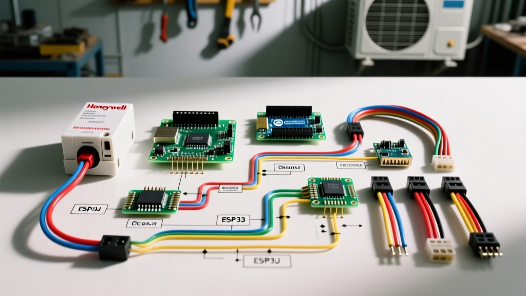

Understanding the Wiring Diagram for Honeywell Fan Limit Switch
The Honeywell fan limit switch (primarily the L4064 and L4006 series) is a critical bimetallic control device in forced-air heating systems. It serves a dual purpose: it activates the blower motor when the heat exchanger reaches a specific temperature, and it acts as a high-limit safety cutoff to shut down the gas valve if the plenum overheats. For electrical professionals and advanced DIYers working from a panel and breaker perspective, correctly interpreting the wiring diagram for Honeywell fan limit switch configurations is essential to prevent control board damage, breaker trips, and fire hazards.
In 2026, while many new furnaces utilize integrated furnace control (IFC) boards with discrete thermistors, millions of legacy and commercial makeup-air units still rely on line-voltage and low-voltage mechanical limit switches. This guide breaks down the exact terminal designations, the infamous factory jumper trap, and the breaker panel safety protocols required for a flawless installation.
Decoding the Terminal Designations
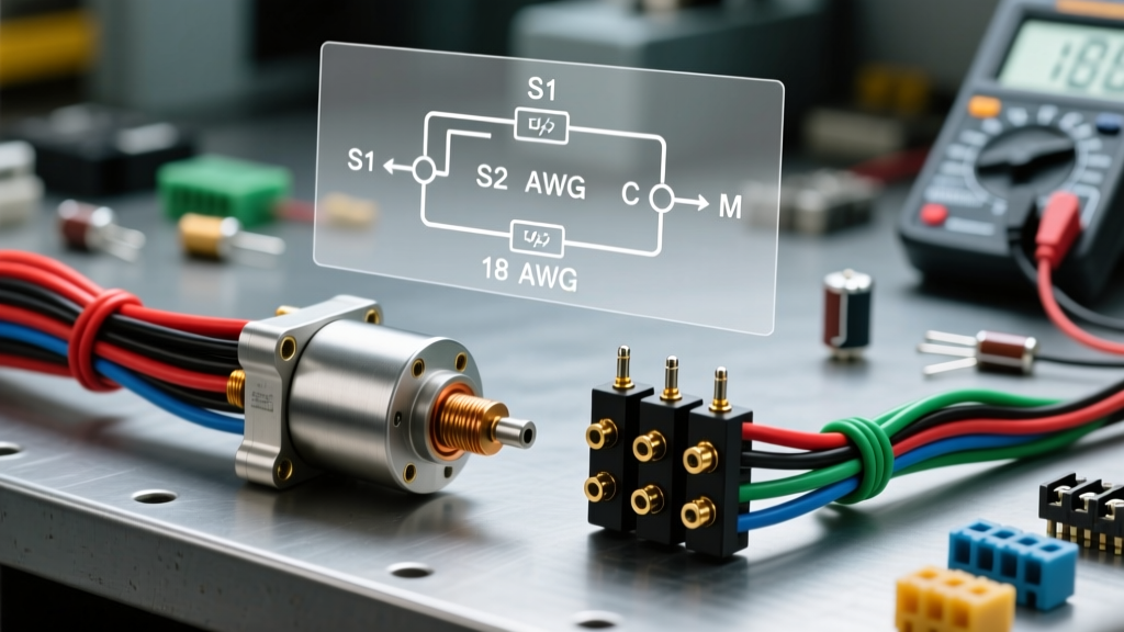
The standard Honeywell L4064B (which includes a manual override switch) and L4064W models feature four primary screw terminals. Understanding what each terminal does is the first step in reading the wiring diagram for Honeywell fan limit switch setups.
- Terminal 1 (Line In / Fan Switch Common): Receives the incoming 120V AC line voltage from the HVAC disconnect or breaker panel. In low-voltage fan control setups, this terminal is often left unused or repurposed depending on the specific control board architecture.
- Terminal 2 (Fan Load / Fan Switch Normally Open): Outputs 120V AC to the blower motor when the bimetallic element senses the "Fan ON" temperature. The internal switch closes to complete the circuit.
- Terminal 3 (Limit Out / Normally Closed): Connects to the gas valve or IFC board limit circuit. Under normal conditions, this circuit is closed, allowing 24V AC (or line voltage in older systems) to pass through to the gas valve.
- Terminal 4 (Limit In / Common): Receives the incoming voltage for the high-limit safety circuit from the transformer or control board.
Note: The L4006 series is a limit-only switch and typically only utilizes two terminals (equivalent to 3 and 4) to break the gas valve circuit on high heat.
The Critical Factory Jumper: Line Voltage vs. Low Voltage
The most common and destructive mistake made when wiring a Honeywell L4064 switch involves the factory-installed jumper wire. This is a vital E-E-A-T insight that separates novice installers from seasoned HVAC electricians.
WARNING: The 120V/24V Backfeed Trap
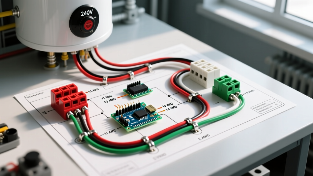
Out of the box, Honeywell installs a small metal jumper between Terminal 1 and Terminal 2. This jumper is designed only for line-voltage fan control systems where the limit switch directly switches 120V to the blower motor. If your furnace uses a modern IFC board that controls the blower via low-voltage relays, you must remove this jumper. Leaving it in place will backfeed 120V line voltage directly into the 24V control board circuit, instantly destroying the IFC board and potentially tripping the main HVAC breaker.
How to Configure the Jumper
| System Type | Blower Control Method | Jumper Status (Terminals 1 & 2) | Wiring Action Required |
|---|---|---|---|
| Legacy Line-Voltage | Limit switch directly powers 120V blower | KEEP Jumper Installed | Wire 120V Hot to Term 1, Blower Hot to Term 2. |
| Modern IFC Board | Control board relay powers blower | REMOVE Jumper Completely | Use only Terminals 3 & 4 for the 24V high-limit safety loop. |
| Commercial Makeup Air | External contactor controls blower | REMOVE Jumper | Wire Terminals 3 & 4 in series with the contactor coil. |
Breaker Panel & Disconnect Safety Protocols
Working on the wiring diagram for Honeywell fan limit switch components requires strict adherence to NFPA 70 National Electrical Code (NEC) standards, specifically regarding disconnecting means and overcurrent protection.
1. Identify and Lock Out the Correct Breaker
Residential air handlers and gas furnaces are typically fed by a dedicated 15A or 20A, 120V single-pole breaker in the main electrical panel. Larger commercial units may use a 240V double-pole breaker. Before removing the blower compartment door, locate this breaker and switch it to the OFF position. Utilize a lockout/tagout (LOTO) device if working in a shared mechanical room.
2. Verify the Local Disconnect
NEC Article 430 requires a local disconnecting means within sight of the HVAC equipment. This is usually a standard 15A/20A toggle switch or a pull-out disconnect box mounted directly adjacent to the furnace. Ensure this local disconnect is also in the OFF position.
3. Test Before You Touch
Never assume the wiring diagram matches the physical installation. Previous technicians may have miswired the line voltage. Use a Category III (CAT III) or Category IV (CAT IV) digital multimeter to test for voltage between Terminal 1 and a known ground. You must read 0.00V before touching the terminal screws. If you read 120V, trace the backfeed to the breaker panel immediately.
Field Adjustments: Temperature Setpoints and Cam Settings
The Honeywell L4064 features three adjustable temperature cams inside the dial housing. According to Air-Conditioning, Heating, and Refrigeration Institute (AHRI) best practices, these should be set to optimize efficiency while preventing heat exchanger stress.
- Fan ON (Upper Cam): Factory set to 130°F (54°C). Adjust between 100°F and 140°F. Setting this too low will cause the blower to push cold air into the living space during the initial heat-up phase. Setting it too high risks tripping the high limit before the blower engages.
- Fan OFF (Lower Cam): Factory set to 100°F (38°C). Adjust between 70°F and 110°F. This dictates how long the blower runs after the burners shut off to extract residual heat from the plenum. A 30-degree differential (130°F ON / 100°F OFF) is standard for 80% AFUE furnaces.
- High Limit (Red Cam): Factory set to 200°F (93°C). Adjust between 180°F and 220°F. Never exceed the maximum temperature rating stamped on the furnace manufacturer's data plate. Setting this above 220°F can cause catastrophic heat exchanger failure and void the equipment warranty.
Physical Installation and Bimetallic Element Clearance
When replacing the switch, the physical mounting is just as critical as the electrical wiring. The bimetallic sensing element must be inserted through the plenum casing. Ensure the element is fully extended and does not touch the metal walls of the heat exchanger or the plenum casing. Direct metal-to-metal contact will conduct heat faster than the ambient air temperature, causing premature limit tripping. Maintain a minimum 1/8-inch clearance around the sensing element.
Troubleshooting Matrix: Common Failure Modes
When the system fails to operate as expected, use this diagnostic matrix to isolate the issue before replacing components.
| Symptom | Probable Cause | Diagnostic Action & Fix |
|---|---|---|
| Blower runs continuously, will not shut off. | Fan switch contacts welded closed, or manual override switch left in 'ON' position. | Check the manual override toggle on the L4064B. If it is 'AUTO', test continuity across Terminals 1 & 2 when cold. If closed, replace the switch. |
| Burners ignite, but shut off after 2-3 minutes. Blower may or may not start. | High limit tripping prematurely due to restricted airflow or faulty bimetal element. | Check air filter and evaporator coil for blockages. Measure plenum temperature with an IR thermometer. If temp is below 180°F but limit trips, replace switch. |
| Control board throws a limit fault code; blower runs but no heat. | Limit circuit (Terminals 3 & 4) is open, or factory jumper was left in, frying the board. | Test continuity across Terminals 3 & 4. If open while cold, replace switch. Inspect IFC board for burnt traces if 120V was backfed. |
| HVAC breaker trips immediately when thermostat calls for heat. | Dead short in the blower motor wiring, or limit switch internal short to ground. | Disconnect blower motor wires at Term 2. Reset breaker. If breaker holds, the motor is shorted. If breaker trips again, the limit switch or wiring is shorted to the chassis. |
Authoritative References and Further Reading
For official schematics, always consult the specific product data sheet provided by Honeywell Home Customer Support & Literature. Wiring diagrams can vary slightly between the L4064B, L4064W, and L4006C models. Always cross-reference the physical wiring diagram printed on the inside of the furnace access panel, as manufacturer-specific control board integrations will supersede generic limit switch wiring guides. Ensure all panel and breaker modifications comply with your local jurisdiction's adoption of the NEC.