
The Thermostat-Motor Interface: Beyond Simple Switches
When HVAC technicians and advanced DIYers search for a wiring diagram for Emerson thermostat models, they are often focused solely on getting the display to turn on. However, from a motor wiring perspective, the thermostat is the critical command center for your system's most expensive components: the blower motor and the condenser fan motor. Whether you are installing a modern smart device like the Emerson Sensi Touch 2 (ST55) or a robust programmable unit like the Emerson 1F80-047, understanding how low-voltage thermostat signals translate into high-voltage motor action is essential for system longevity and efficiency.
Thermostats do not wire directly to 120V or 240V motors. Instead, they utilize 24VAC control circuits to energize relays and contactor coils. A miswired terminal won't just fail to start your system; it can short the 24V transformer, blow the 3A control board fuse, or cause severe cogging in modern ECM (Electronically Commutated Motors). This guide bridges the gap between thermostat wiring diagrams and actual motor control circuits.
Safety and Code Compliance for Class 2 Circuits
Before touching any wires, it is vital to recognize the boundary between line voltage and low voltage. According to NFPA 70 (National Electrical Code) Article 725, thermostat wiring is classified as a Class 2 remote-control circuit. This means it is inherently power-limited (usually under 100VA) and requires different wiring methods than your motor's main power supply.
Expert Warning: Never run 18 AWG thermostat wire in the same conduit or knockouts as 120V/240V motor feed wires. Inductive interference from the motor's startup current can induce phantom voltages in the thermostat wire, leading to ghost signals that cause your blower motor to short-cycle or run continuously.
Decoding the Wiring Diagram for Emerson Thermostat Terminals
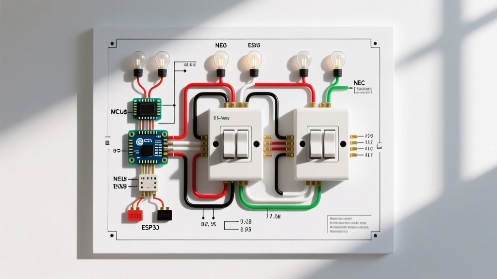
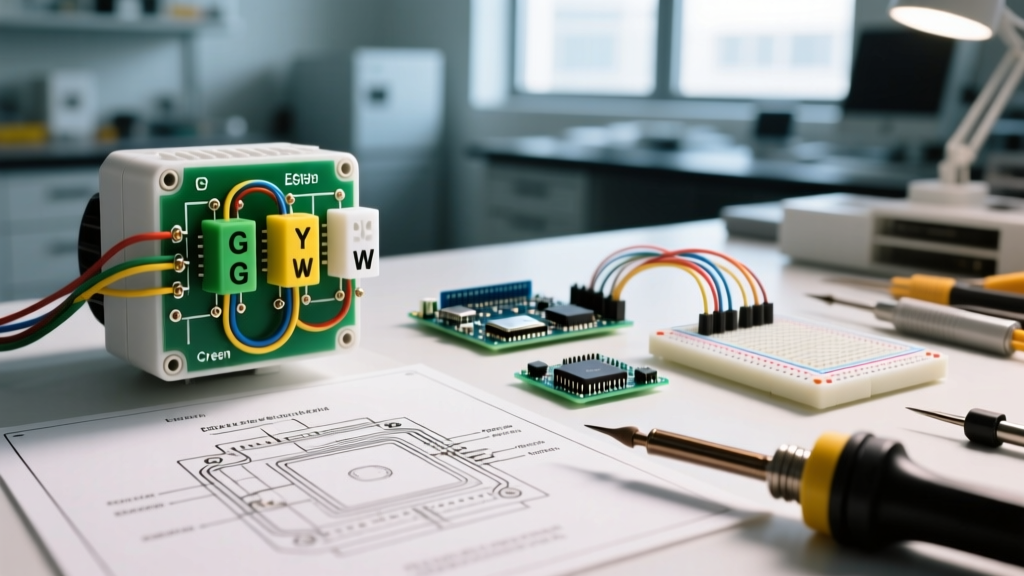
To control HVAC motors, you must understand the specific terminal designations on your Emerson baseplate. Below is the standard matrix for how these low-voltage signals dictate motor behavior.
| Terminal | Standard Wire Color | Target Component | Motor Action Triggered |
|---|---|---|---|
| R / Rc / Rh | Red | 24VAC Transformer Hot | Provides power to all control relays. |
| C | Blue / Black | 24VAC Transformer Common | Completes the circuit for smart thermostats and ECM boards. |
| G | Green | Blower Fan Relay | Energizes relay to send 120V to the indoor blower motor. |
| Y / Y1 | Yellow | Compressor Contactor Coil | Pulls contactor to send 240V to compressor & condenser fan motor. |
| W / W1 | White | Gas Valve / Heat Relay | Initiates heating sequence; eventually triggers blower via limit switch. |
| O / B | Orange | Reversing Valve Solenoid | Switches heat pump mode; alters compressor motor refrigerant flow. |
Step-by-Step: Wiring the G Terminal (Blower Motor Control)
The G terminal is the direct link to your indoor blower motor. When the Emerson thermostat calls for fan-only mode, or when a heating/cooling cycle demands airflow, it closes the internal relay between R and G.
- Verify the Control Board Relay: Trace the Green (G) wire from the Emerson baseplate to the furnace or air handler control board. It should land on the 'G' terminal of the board, not directly on the motor.
- Check the 3A Fuse: Locate the 3A automotive-style ATO blade fuse on the control board. If the G wire shorts to ground (or to the C wire) at the thermostat baseplate, this fuse will blow instantly to protect the 40VA transformer.
- Measure Relay Coil Resistance: If the thermostat sends 24VAC to the G terminal but the blower motor doesn't start, use a multimeter to measure the resistance across the fan relay coil on the control board. A healthy coil will read between 10 and 50 ohms. An infinite reading (OL) means the relay is dead and must be replaced (typically a $15 to $30 part).
The Y Terminal: Contactor Coils and Condenser Fan Motors
The Y terminal controls the outdoor unit. When your Emerson thermostat calls for cooling, it sends 24VAC down the Yellow wire to the outdoor unit's contactor. This 24V signal energizes the contactor's electromagnetic coil, pulling the high-voltage contacts closed and sending 240V simultaneously to the compressor and the condenser fan motor.
Failure Mode - Contactor Chatter: If your Emerson thermostat's Y terminal connection is loose, or if the 18 AWG wire is damaged, the voltage drop across the wire may cause the contactor coil to receive only 18V to 20V instead of a solid 24V. This results in 'contactor chatter'—a rapid clicking sound. This is catastrophic for the condenser fan motor and compressor, as it rapidly cycles line voltage, causing severe thermal stress and winding degradation.
ECM vs. PSC Motors: The C-Wire Imperative
When reviewing any Emerson Sensi wiring diagram, the C (Common) wire is heavily emphasized. This is especially critical depending on the type of blower motor installed in your air handler.
Permanent Split Capacitor (PSC) Motors
Older, single-speed PSC motors rely on simple electromechanical relays on the control board. While an Emerson thermostat can operate without a C-wire on these systems by 'power stealing' (leaking a tiny amount of current through the Y or W circuit to charge its internal battery), it is not recommended.
Electronically Commutated Motors (ECM)
Modern ECM motors (like the GE X13 or Genteq 3.0) feature internal microprocessors and require a continuous, stable 24VAC reference signal. If you install an Emerson Sensi Touch 2 without a C-wire on an ECM system, the power-stealing current will pass through the ECM's control board. This phantom voltage can confuse the motor's logic board, causing the blower to jitter, stall, or throw fault codes. Always connect the C-wire when interfacing with ECM motor systems.
Transformer VA Ratings and Motor Relay Loads
A standard HVAC control transformer is rated for 40VA (Volt-Amps). At 24 volts, this equates to a maximum current capacity of roughly 1.66 Amps (40 / 24 = 1.66). You must account for the inrush current of the motor relays and contactor coils.
- Indoor Fan Relay Coil: ~10 VA
- Outdoor Contactor Coil: ~15 VA
- Emerson Thermostat Draw: ~1.5 VA to 3 VA
- Smart Damper Actuators (Zoning): ~5 VA to 10 VA each
If you are adding a zoning system or multiple high-draw motorized dampers to your Emerson thermostat setup, you may exceed the 40VA limit. When this happens, the 24VAC drops below 19V, and the contactor coil for your condenser motor will fail to pull in. The solution is upgrading the control transformer to a 75VA or 100VA model (costing roughly $35 to $60 in 2026) to ensure adequate amperage for all motor-starting relays.
Troubleshooting Motor Start Failures from the Thermostat
Before replacing a suspected dead blower or condenser motor, verify the thermostat's output. Follow this diagnostic sequence recommended by U.S. Department of Energy HVAC efficiency guidelines:
- Set the Multimeter to AC Voltage (VAC): Place your probes on the R and C terminals at the Emerson baseplate. You should read between 24VAC and 28VAC.
- Force a Fan Call: Set the thermostat to 'Fan On'. Measure between the G terminal and the C terminal. You should read 24VAC.
- Check the Control Board: If you have 24VAC at the thermostat's G terminal, but 0VAC at the control board's G terminal, you have a broken 18 AWG green wire inside the wall.
- Verify Line Voltage at the Motor: If the control board G terminal has 24VAC, and the fan relay clicks, but the motor doesn't spin, use a non-contact voltage tester or multimeter to check for 120VAC at the motor's pigtail connections. If 120V is present but the motor is dead (and the run capacitor tests within 5% of its microfarad rating), the motor windings are open, and the motor must be replaced.
Frequently Asked Questions
Can I wire an Emerson thermostat directly to a 120V attic fan motor?
No. Emerson thermostats are designed strictly for 24VAC Class 2 HVAC control circuits. To control a 120V line-voltage attic fan, you must use the Emerson thermostat to trigger a 24V coil of a heavy-duty isolation relay (like an Honeywell R8222), which will then switch the 120V line voltage to the motor.
Why does my blower motor run for 60 seconds after the thermostat stops calling for cooling?
This is a feature, not a wiring error. Many modern Emerson thermostats and HVAC control boards utilize a 'blower off delay' to extract residual cooling from the evaporator coil. The thermostat opens the Y circuit to stop the outdoor condenser motor, but keeps the G circuit closed for 60 to 90 seconds to maximize energy efficiency and dehumidification.
What wire gauge should I use for a 60-foot run to the outdoor condenser contactor?
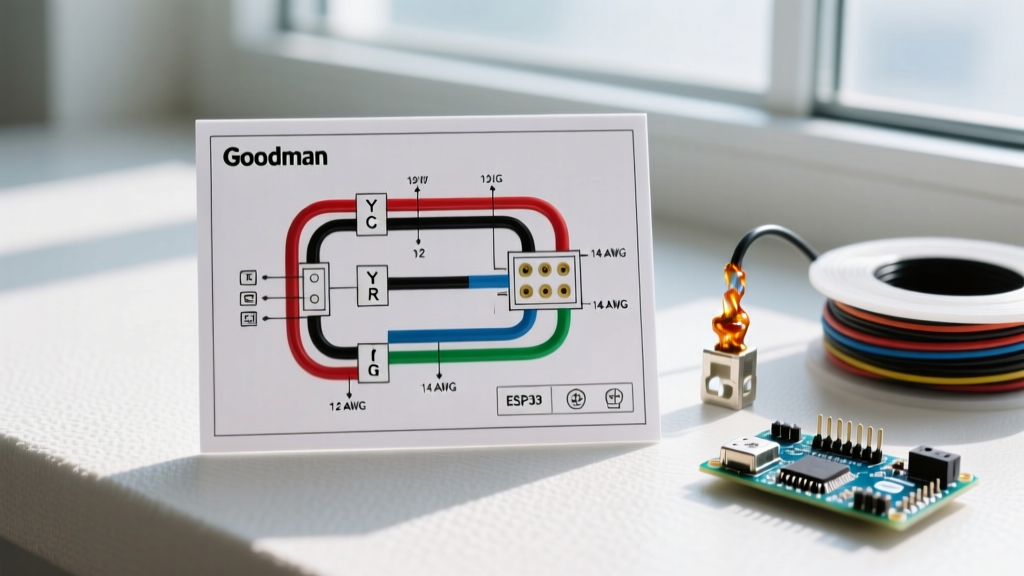
While 18 AWG is standard for indoor thermostat wiring, a run exceeding 50 feet to the outdoor unit's Y and C terminals can suffer from voltage drop, leading to weak contactor engagement. For runs between 50 and 100 feet, upgrade to 16 AWG or 14 AWG stranded copper wire to ensure a solid 24VAC reaches the condenser motor's contactor coil.