
Decoding the Standard Ceiling Fan Electrical Wiring Diagram
Upgrading or installing a new ceiling fan involves more than just hanging a heavy motor and attaching blades. The core of a successful, code-compliant installation lies in understanding the ceiling fan electrical wiring diagram specific to your wall switch configuration and fixture capabilities. Whether you are installing a smart-enabled Minka-Aire Artemis or a classic Hunter Dempsey, the fundamental electrical principles remain governed by the National Electrical Code (NEC) and UL 507 safety standards.
Modern ceiling fans often feature integrated LED light kits, remote-control receivers, and reversible DC motors. These additions complicate the standard wiring matrix. In this comprehensive reference guide, we will break down the exact color-code mappings, dual-switch configurations, and critical edge cases that DIYers and professional electricians must navigate to ensure safe, hum-free, and reliable operation.
Anatomy of Fan Wiring: Color Codes and Functions
Before connecting any wire nuts or lever connectors, you must map the house wiring to the fan’s internal leads. Most North American residential wiring utilizes NM-B (Romex) cable, while the fan manufacturer provides stranded THHN leads. Here is the universal color-code translation for standard AC ceiling fans:
- House Black (Hot): Supplies unswitched or switched 120V power to the fan motor or wall switch.
- House Red (Secondary Hot): Used in 3-wire setups to supply independent power to the light kit.
- House White (Neutral): Completes the circuit. Must be connected to the fan’s white neutral lead and any smart receiver modules.
- House Bare/Green (Ground): Safety ground. Must be bonded to the fan’s green ground wire and the metal electrical box.
- Fan Blue (Light Kit Hot): Carries power specifically to the integrated light fixture.
Wire Gauge and Circuit Amperage Matrix
Selecting the correct NM-B cable is critical to prevent voltage drop and overheating, especially when running long distances from the breaker panel. According to National Fire Protection Association (NFPA) NEC guidelines, the following wire gauges apply to 120V residential fan circuits:
| Circuit Breaker | NM-B Wire Gauge | Max Run Length (3% Drop) | Typical Application |
|---|---|---|---|
| 15 Amp | 14 AWG (14/2 or 14/3) | 50 feet | Standard bedroom fans without heavy lighting loads |
| 20 Amp | 12 AWG (12/2 or 12/3) | 60 feet | Living rooms, dual-switch setups, or fans with high-wattage halogen kits |
| 20 Amp (Long Run) | 10 AWG (10/3) | 85+ feet | Large great rooms, vaulted ceilings with extended downrods |
Scenario A: The Dual Switch Configuration (Independent Control)
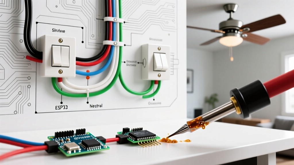
The most highly sought-after ceiling fan electrical wiring diagram is the dual-switch setup. This allows the user to control the fan motor and the light kit from two separate toggles on a single wall plate (e.g., a Leviton 15A Double Rocker Switch).
Step-by-Step Dual Switch Wiring Procedure
- Verify Power is Off: Use a non-contact voltage tester (like the Klein Tools NCVT-2) at the ceiling box and the wall switch to confirm the circuit is dead.
- Run 12/3 NM-B Cable: You must use a 3-wire cable (Black, Red, White, Ground) from the dual wall switch box up to the ceiling electrical box. The 12/2 cable used for single switches cannot support independent control.
- Wire the Wall Switches:
- Connect the incoming House Hot (Black) to the common terminal of both switches using a pigtail wire.
- Connect the Black wire of the 12/3 cable to the load terminal of the Fan Switch.
- Connect the Red wire of the 12/3 cable to the load terminal of the Light Switch.
- Wire the Ceiling Canopy:
- Connect the 12/3 Black wire to the Fan’s Black wire (Motor).
- Connect the 12/3 Red wire to the Fan’s Blue wire (Light Kit).
- Connect all White (Neutral) wires together using a Wago 221 lever nut.
- Bond all Ground wires to the metal ceiling box grounding screw.
Scenario B: Single Switch with Remote Control Receiver
If your home is pre-wired with only a 12/2 cable (single switch), you can still achieve independent fan and light control by installing a remote-control receiver in the fan canopy. Brands like Hunter (SimpleConnect) and Hampton Bay utilize canopy-mounted RF receivers.
Expert Warning: When wiring a remote receiver, the wall switch must remain in the "ON" (closed) position permanently. The receiver requires constant 120V hot and neutral power to maintain its RF pairing and memory states. Using a standard wall dimmer switch on a circuit with a canopy receiver will destroy the receiver's internal TRIAC and cause severe motor humming.
To wire the receiver, the House Black (Hot) connects to the Receiver's "AC IN L" (usually black), and the House White (Neutral) connects to "AC IN N" (white). The receiver's output wires then map directly to the fan's Black, Blue, and White leads. Ensure the thin antenna wire is left uncut and routed outside the metal canopy to prevent signal shielding.
NEC Compliance: Box Ratings and Weight Limits
A critical failure point in ceiling fan installations is the use of standard light-fixture electrical boxes. According to EPA ENERGY STAR and UL safety specifications, ceiling fans generate significant dynamic torque and vibration.
NEC Article 314.27 explicitly mandates that ceiling fans must be supported by an outlet box specifically listed and marked for fan support.
- Standard Fan-Rated Box: Rated for fans up to 35 lbs.
- Heavy-Duty Fan-Rated Box: Rated for fans up to 70 lbs (required for large 60-inch+ blade spans or solid wood blade models).
If you are retrofitting an older home, use a heavy-duty brace bar (such as the Saf-T-Brace) that spans across the ceiling joists to provide independent structural support, bypassing the drywall entirely.
Troubleshooting Common Wiring Edge Cases
Even with a perfect ceiling fan electrical wiring diagram, real-world variables can introduce electrical anomalies. Here is how to diagnose the most common issues:
1. Severe Motor Humming on Low Speed
Cause: Incompatible wall dimmer. Standard LED/CFL dimmers (like the Lutron Diva DVCL-153P) chop the AC sine wave in a way that induces harmonic resonance in the fan's stator windings.
Solution: Replace the wall switch with a dedicated fan speed control (e.g., Lutron Diva DVELV-300P or a specific fan-rated toggle) that utilizes stepped voltage reduction rather than TRIAC phase-cutting.
2. Flickering LED Light Kit
Cause: Loose neutral connection or incompatible LED driver. If the flickering only occurs when the fan is on "High", the vibration is likely loosening a poorly seated wire nut.
Solution: Strip the wires back by 5/8 inch and use Wago 221 lever connectors. These provide a vibration-resistant, gas-tight connection that traditional twist-on wire nuts cannot guarantee in high-torque environments.
3. AFCI Breaker Nuisance Tripping
Cause: Modern homes require Arc Fault Circuit Interrupter (AFCI) breakers. Cheap, unshielded RF remote receivers can emit electromagnetic interference (EMI) that mimics an arc fault signature, tripping the breaker.
Solution: Upgrade to a shielded receiver module or hardwire the fan to a dual-switch setup, eliminating the RF receiver entirely. Refer to the Hunter Fan Company Installation Guidelines for specific bypass procedures on smart models.
4. Fan Runs Backwards Despite Switch Position
Cause: A failed run capacitor. The capacitor (typically a silver or black rectangular block rated at 4.5µF to 6µF / 250VAC) dictates the phase shift required for motor direction and starting torque. If it degrades, the fan may start in reverse or stall entirely.
Solution: Open the switch housing cup, locate the capacitor, match the exact microfarad (µF) rating, and solder/splice in a replacement. Do not mix up the wire colors on a multi-wire capacitor, as this will short the auxiliary winding.
Final Safety Verification
Once all connections are made and the canopy is secured, restore power at the breaker panel. Test the fan on all three speeds, verify the light kit dimming function (if applicable), and ensure the grounding path is intact using a standard 3-prong receptacle tester adapted for the fixture. Proper execution of your ceiling fan electrical wiring diagram ensures decades of quiet, efficient airflow and illumination.