
The Evolution of Turn Signals in Custom Motor Builds
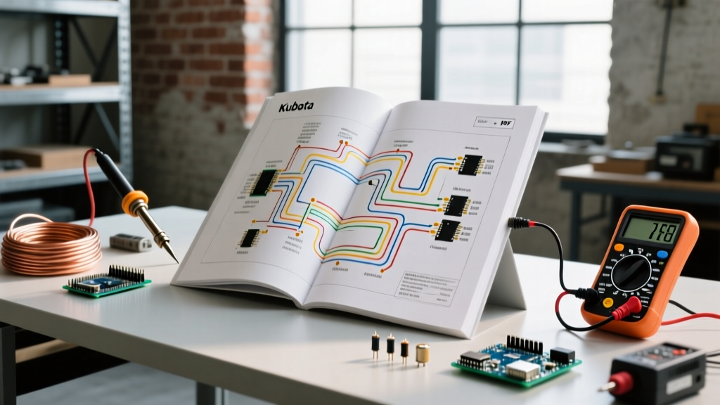
Whether you are wiring a custom electric vehicle (EV) conversion, restoring a vintage motorcycle, or upgrading a 48V golf cart with a modern street-legal lighting kit, the turn signal circuit is a critical safety system. In modern motor builds, the shift from incandescent bulbs to Light Emitting Diodes (LEDs) has introduced a widespread electrical headache: hyperflashing or complete signal failure. The root cause almost always traces back to the flasher unit. Understanding and correctly implementing a wiring diagram for flasher relay circuits is the definitive solution to this problem.
Unlike standard automotive chassis that use heavy steel frames for grounding, many custom motor builds, golf carts, and EVs utilize fiberglass, carbon fiber, or powder-coated aluminum tubs. This makes traditional 2-pin thermal relays obsolete and unreliable. In this comprehensive motor wiring tutorial, we will dissect the exact wiring topologies, component selections, and troubleshooting frameworks required to build a bulletproof LED turn signal system in 2026.
Thermal vs. Electronic Flasher Relays: What Motor Builders Need to Know
To wire a system correctly, you must first understand the physics of the switch. Older vehicles relied on thermal flashers, while modern motor builds demand electronic or solid-state relays. According to the NHTSA lighting equipment guidelines, turn signal flash rates must remain within a specific cadence (typically 60 to 120 flashes per minute) to comply with federal safety standards.
| Relay Type | Operating Mechanism | Load Dependency | Best Application | Avg. Cost (2026) |
|---|---|---|---|---|
| Thermal (Bimetallic) | Heats up and bends a metal strip to break the circuit. | High (Requires 2-4 Amps minimum) | Stock vintage cars with incandescent bulbs. | $5 - $9 |
| Electronic (IC Driven) | Uses an integrated circuit and MOSFET to switch power. | Low (Operates from 0.1W to 150W) | LED swaps, golf carts, EV conversions. | $12 - $18 |
| Solid-State (Digital) | Microcontroller-based with adjustable flash rates. | None (Can drive single 1W LED) | High-end custom motorcycles, CAN-bus systems. | $35 - $65 |
Expert Insight: If you wire an LED turn signal kit using a standard thermal relay (like the common Tridon ST12), the LEDs will draw roughly 0.2 Amps total. This is not enough current to heat the bimetallic strip, resulting in the lights either staying solid or flashing so rapidly they appear as a strobe. You must swap to an electronic relay.
Decoding the Standard Wiring Diagram for Flasher Relay Setups
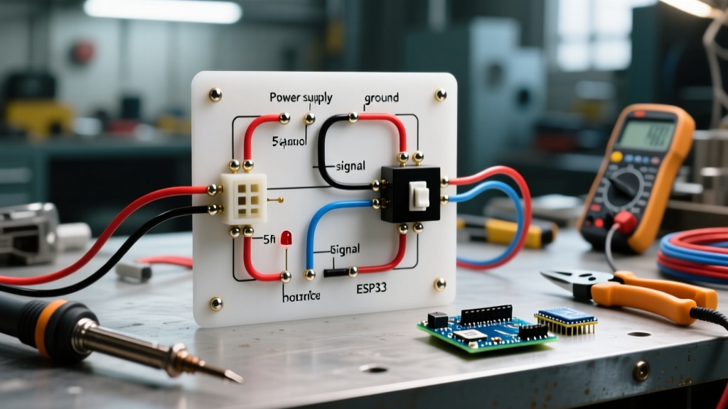
When consulting a wiring diagram for flasher relay installations, you will encounter two primary pin configurations: 2-pin and 3-pin. Selecting the correct one depends entirely on your motor build's chassis composition and grounding strategy.
The 2-Pin Configuration (B and L)
The 2-pin relay features a B (Battery/Power) terminal and an L (Load) terminal. This relay is designed to ground itself internally through the turn signal switch and the bulb sockets back to the vehicle's negative battery terminal. This works perfectly on steel-bodied vehicles where the chassis acts as a universal ground plane. However, in golf carts with plastic bodies or EVs with isolated battery grounds, a 2-pin relay will fail to complete the circuit.
The 3-Pin Configuration (B, L, and E/P)
The 3-pin relay adds an E (Earth/Ground) or P (Panel) terminal. This is the gold standard for custom motor builds. By providing a dedicated ground wire directly to the battery's negative terminal or a verified bare-metal chassis point, you bypass the need for the switch or bulb housings to act as the ground return path. For detailed relay switching logic and circuit theory, resources like the All About Circuits DC textbook provide excellent foundational knowledge on why dedicated ground paths prevent voltage drop issues.
Step-by-Step Motor Application: Wiring a 3-Pin Electronic Relay
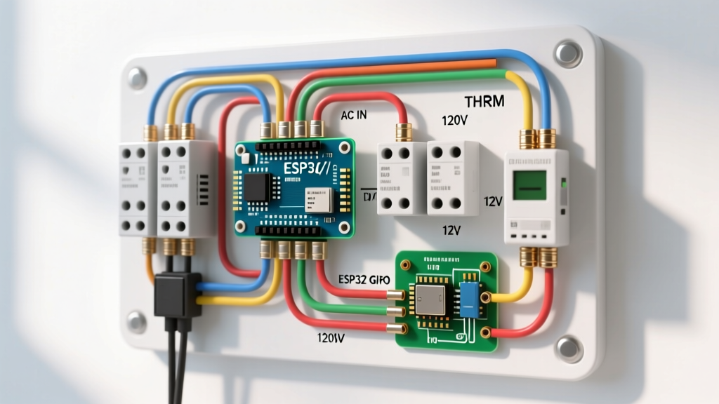
Let us walk through a real-world scenario: Wiring a street-legal turn signal kit on a 48V Club Car golf cart using a Novita LM470 3-pin electronic flasher relay. Because the golf cart runs on a 48V battery bank, and the relay and LEDs are 12V components, a DC-DC step-down converter (buck converter) is mandatory.
- Step 1: Establish the 12V Power Source (B Pin)
Connect the output of your 48V-to-12V buck converter to a fuse block. Run a 16 AWG wire from a 10A fused slot to the B (Battery) pin on the flasher relay. Crucially, this wire should be routed through an ignition-switched toggle so the relay does not drain the 12V accessory battery when the cart is parked. - Step 2: Route the Load Wire (L Pin)
Connect a 16 AWG wire from the L (Load) pin to the center common terminal of your turn signal combination switch. From the left and right output terminals of the switch, run 18 AWG wires to the respective front and rear LED turn signal bulbs. - Step 3: Secure the Dedicated Ground (E Pin)
This is where most DIY motor builds fail. Do not simply wrap the E (Earth) wire around a painted frame bolt. Run a 16 AWG wire from the E pin directly to the negative terminal of your 12V accessory battery, or use a ring terminal to bolt it to a sanded, bare-metal section of the chassis, sealed with dielectric grease to prevent corrosion. - Step 4: Ground the LED Housings
Even with a 3-pin relay, the LED bulbs themselves require a ground to illuminate. Run 18 AWG ground wires from the negative contact of each LED bulb housing back to your main 12V negative bus bar.
Troubleshooting Common Flasher Relay Failures in Motorized Equipment
Even with a perfect wiring diagram for flasher relay circuits, environmental factors and vibration in motor builds can cause faults. Use a digital multimeter (DMM) to diagnose these common failure modes:
- Symptom: Turn signals stay solidly lit, never flashing.
Diagnosis: The E (Ground) pin on the relay has lost connection. The internal IC cannot complete its timing circuit without a ground reference. Fix: Check continuity between the E pin and the battery negative terminal. - Symptom: Hyperflashing (flashing twice as fast as normal).
Diagnosis: You are either accidentally using a thermal relay, or one of your LED bulbs has burned out, dropping the total circuit resistance below the relay's minimum threshold (if using a load-dependent electronic relay). Fix: Verify the relay model number and test all bulbs. - Symptom: Lights flash erratically or dimly.
Diagnosis: Severe voltage drop on the B (Power) wire. In 12V systems, if voltage at the B pin drops below 10.5V under load, the internal MOSFET will struggle to switch. Fix: Measure voltage at the B pin while the signals are active. If it reads below 11.5V, upgrade the B wire from 16 AWG to 14 AWG.
Sourcing the Right Components for 2026 Motor Builds
When sourcing components for your wiring diagram for flasher relay layouts, avoid cheap, unbranded relays from overseas marketplaces. These often lack internal flyback diodes, which can send voltage spikes back into your motor build's delicate ECU or motor controller when the relay switches off.
Look for established automotive brands. The Novita LM470 (approx. $16) is a legendary 3-pin electronic relay capable of handling mixed LED and incandescent loads, making it perfect for custom builds where you might have an LED front signal but an incandescent rear tail/brake combo. The Tridon EL13 (approx. $14) is an excellent 2-pin alternative for steel-bodied vintage motorcycles. Always verify the relay's voltage rating; while 12V is standard, some heavy-duty golf carts and forklifts utilize 24V or 36V systems, requiring specialized heavy-duty flashers rated for those specific DC voltages.
Final Wiring Best Practices
Always use heat-shrink butt connectors with adhesive lining rather than standard vinyl electrical tape for any connections exposed to the elements. In motor builds, vibration is the enemy of electrical continuity. Secure your relay to the chassis using a rubber-grommeted mounting bracket to absorb high-frequency motor harmonics, ensuring your turn signals operate flawlessly for the life of the vehicle.