
Mastering the Electric Hot Water Heater Electrical Wiring Diagram
Wiring a standard 240-volt electric storage water heater is one of the most common residential electrical tasks, yet it leaves zero margin for error. Whether you are installing a reliable A.O. Smith ProLine or a Rheem Performance series unit, understanding the exact electric hot water heater electrical wiring diagram is critical for safety, code compliance, and appliance longevity. While heat pump models are gaining traction in 2026, traditional 4500W dual-element resistance heaters remain a staple in millions of homes.
This step-by-step walkthrough bypasses generic advice and dives deep into the specific measurements, torque specifications, and National Electrical Code (NEC) requirements you need to execute a flawless installation. According to the National Fire Protection Association (NFPA) 70 National Electrical Code, water heaters are classified as continuous or non-continuous loads depending on their specific design, dictating strict overcurrent protection rules under Article 422.
Prerequisites and Specialized Tooling
Before touching a single wire, ensure you have the correct materials. Using undersized wire or the wrong breaker type is a leading cause of electrical fires and failed heating elements.
- Cable: 10/2 NM-B (Romex) copper cable with a bare ground wire. (Brands like Southwire SIMpull are industry standard).
- Breaker: 30-Amp, 240V double-pole breaker (e.g., Square D QO230 or Eaton BR230, matching your panel brand).
- Torque Screwdriver: Klein Tools 69062 or similar, calibrated to your breaker's specific inch-pound requirement.
- Multimeter: Fluke 117 True RMS or equivalent CAT III rated meter for safe voltage verification.
- Safety Gear: Class 0 rubber insulating gloves and safety glasses.
Critical Safety Warning: Never rely solely on a breaker being in the 'OFF' position. The OSHA Electrical Safety Standards mandate Lockout/Tagout (LOTO) procedures. Always verify the circuit is dead with a non-contact voltage tester and a multimeter before opening the panel or the heater's junction box.
Sizing Your Circuit: Wire Gauge and Breaker Matrix
The wattage of your water heater's elements dictates the wire gauge and breaker size. Most modern 40 to 50-gallon electric water heaters utilize dual 4500-watt elements. Because these elements operate non-simultaneously (only one turns on at a time), the maximum current draw is based on a single 4500W element.
| Element Wattage | Max Amperage (at 240V) | Minimum NEC Wire Gauge | Required Breaker Size | Notes & Edge Cases |
|---|---|---|---|---|
| 3000W | 12.5A | 14 AWG (12 AWG Rec.) | 15A or 20A 2-Pole | Rare in modern 40+ gal tanks; common in point-of-use. |
| 3800W | 15.8A | 12 AWG | 20A 2-Pole | Often found in 30-gallon or low-boy models. |
| 4500W | 18.75A | 10 AWG | 30A 2-Pole | Industry standard for 40-50 gallon residential tanks. |
| 5500W | 22.9A | 10 AWG | 30A 2-Pole | High-recovery models; requires robust 10 AWG connections. |
Step 1: Panel Connection and Torque Specifications
Your journey begins at the main service panel. For a standard 4500W heater, you will be installing a 30A double-pole breaker.
- Install the Breaker: Snap the 30A 2-pole breaker into an available adjacent slot in your panel. Ensure it seats firmly onto both hot bus bars.
- Prepare the 10/2 NM-B Cable: Strip back 3/4 inch of insulation from the black and white conductors. Crucial Step: Wrap the white wire's exposed end and the last 2 inches of its insulation with black or red electrical tape. This permanently identifies it as a hot leg, not a neutral, per NEC Article 200.7.
- Terminate the Hot Legs: Insert the black wire into one breaker terminal and the taped white wire into the other.
- Apply Precise Torque: Tighten the terminal screws using your torque screwdriver. For a Square D QO breaker, the manufacturer specifies 35 in-lbs. Under-torquing causes arcing and thermal failure; over-torquing strips the aluminum bus stabs.
- Ground Connection: Terminate the bare copper ground wire to the panel's dedicated equipment grounding bar. Never bond the ground to the neutral bar in a subpanel.
Step 2: Routing and Securing the Cable
Run the 10/2 cable from the panel to the water heater location. According to NEC Article 334.30, NM-B cable must be secured and supported by staples, cable ties, or straps at intervals not exceeding 4.5 feet (1.4 meters) and within 12 inches of the junction box. Use insulated cable staples to prevent crushing the jacket, which can compromise the internal wire insulation over time.
Step 3: Junction Box and Thermostat Wiring Walkthrough
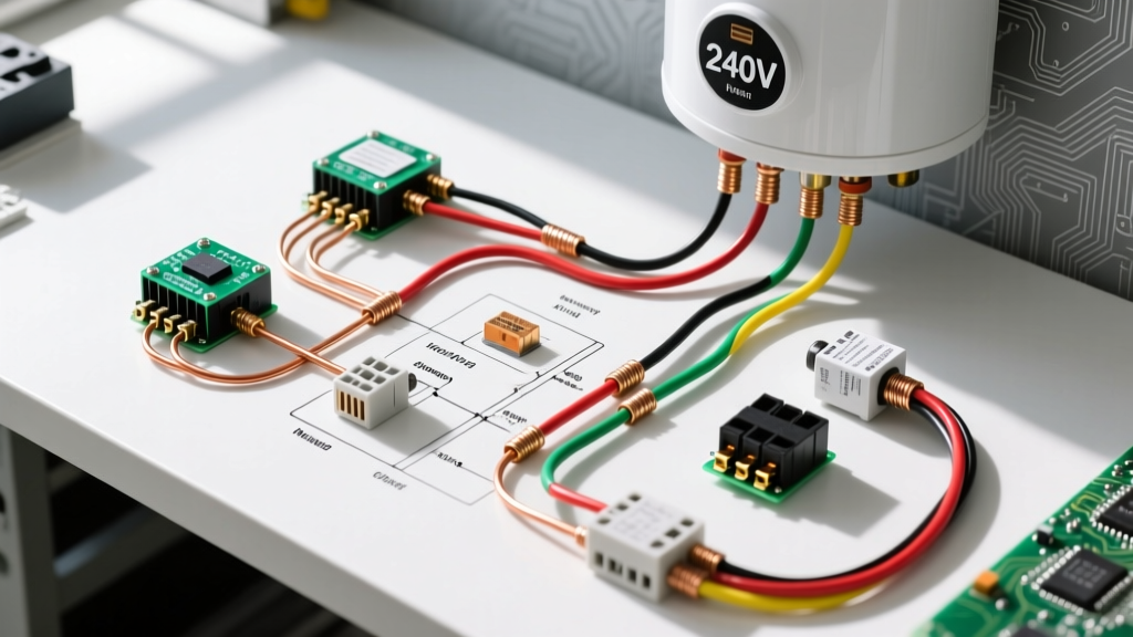
Standard electric water heaters utilize a non-simultaneous dual-element system. The upper thermostat acts as the primary controller, prioritizing the top element to deliver a quick half-tank of hot water before passing power to the lower thermostat. Here is how to wire the internal junction box and access panels:
Grounding the Chassis
Before connecting the hot legs, establish the safety ground. Connect the bare copper ground wire from your 10/2 cable to the green grounding screw inside the heater's junction box. Run a separate 10 AWG bare copper or green-insulated jumper wire from this junction box ground to the grounding lug located on the lower tank jacket. This ensures the entire metal tank is bonded to earth ground.
Connecting the Thermostats
Remove the upper and lower access panels, insulation, and safety shields. You will see the thermostats and elements.
- Line 1 (Black Wire): Connect the black hot wire from your cable to the L1 terminal on the upper thermostat.
- Line 2 (Taped White Wire): Connect the taped white hot wire to the L3 terminal on the upper thermostat.
- Inter-thermostat Jumpers: The manufacturer pre-installs jumper wires connecting the upper thermostat to the lower thermostat. Ensure these are tight. They carry L1 and L3 down to the L2 and L4 terminals on the lower thermostat.
- Element Connections: The thermostats route power to the elements. Verify that the heating element terminal nuts are snug (usually 11/32-inch or 3/8-inch). Loose element connections create high resistance, leading to melted wire spades and catastrophic element failure.
Step 4: Final Testing and Commissioning
Before turning the power on, the U.S. Department of Energy Water Heating Guide emphasizes one absolute rule: Never energize the elements while the tank is empty. The elements will dry-fire and burn out in seconds. Ensure the tank is completely full of water and all air is purged from the hot water lines before proceeding.
- Visual Inspection: Double-check all terminal screws. Ensure no stray copper strands are touching the metal chassis or adjacent terminals.
- Energize the Circuit: Turn on the 30A double-pole breaker at the main panel.
- Voltage Verification: Set your Fluke 117 multimeter to AC Voltage. Place one probe on L1 and the other on L3 at the upper thermostat. You should read between 235V and 245V.
- Ground Fault Check: Place one probe on L1 and the other on the bare metal tank (or ground screw). You should read approximately 120V. Repeat for L2. If you read 0V on one leg and 240V on the other to ground, you have a lost leg or a miswired breaker.
- Thermostat Calibration: Set both the upper and lower thermostats to 120°F (49°C). This balances energy efficiency with scalding prevention, while keeping the temperature high enough to mitigate Legionella bacteria growth in standard residential use.
Common Wiring Mistakes and Edge Cases
Even experienced DIYers can fall into specific traps when following an electric hot water heater electrical wiring diagram. Avoid these critical errors:
1. The 'Simultaneous' Misconception
Many homeowners attempt to wire both elements to run simultaneously to get hot water faster. Unless your unit specifically states 'Simultaneous Operation' and your electrical service can support a 60A+ dedicated circuit, doing this will instantly trip a standard 30A breaker and risk melting 10 AWG wire. Stick to the factory non-simultaneous wiring.
2. Using the White Wire as a Neutral
A 240V water heater does not use a neutral wire. The white wire in a 10/2 cable is strictly used as a second hot leg. Failing to re-identify it with black or red tape is a direct NEC violation and creates a severe shock hazard for future electricians who might assume the white wire is dead.
3. Ignoring the High-Limit Reset (ECO)
If your upper thermostat's Energy Cut Off (ECO) red reset button trips immediately upon wiring, do not simply reset it. This indicates a failed upper thermostat, a shorted upper element, or wiring that is bypassing the thermostat entirely. Use your multimeter's continuity setting to test the elements (expect 12 to 16 ohms for a 4500W element) and check for continuity between the element terminals and the tank shell to rule out a grounded element.
Summary
Executing a safe and code-compliant installation requires more than just matching wire colors. By adhering to precise torque specifications, properly identifying the secondary hot leg, and understanding the non-simultaneous logic of the thermostats, you ensure your water heater operates efficiently and safely for its entire 10-to-15-year lifespan. Always consult the specific manufacturer's wiring schematic located on the inside of your unit's access panels, as minor variations exist between brands like Bradford White, Rheem, and A.O. Smith.