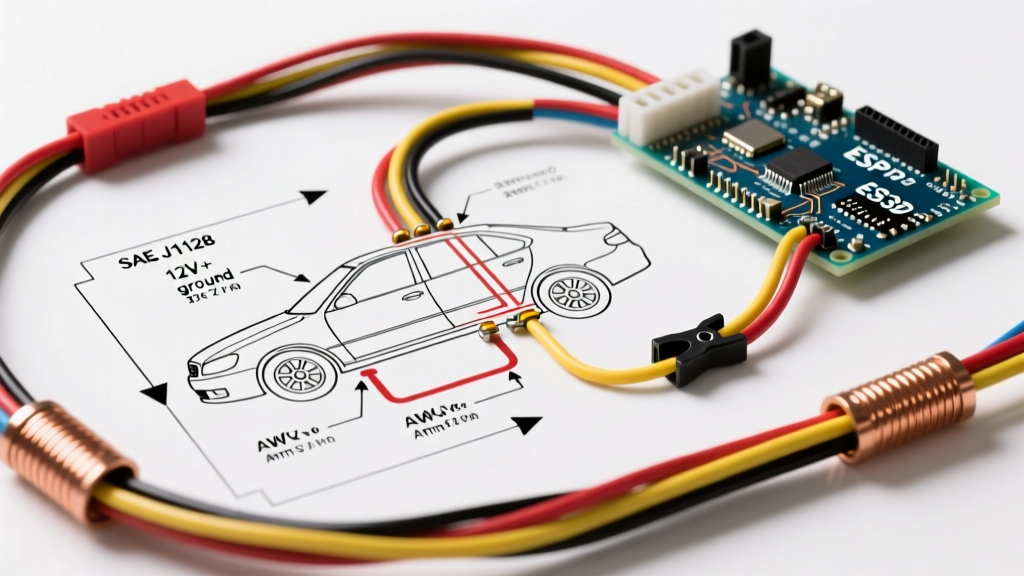

Interpreting a wiring diagram for cars requires more than just tracing lines from a battery to a headlight. Modern vehicles are complex networks of sensors, control modules, and high-current actuators. Whether you are diagnosing a parasitic draw, installing an aftermarket amplifier, or troubleshooting a CAN bus communication fault, understanding wire gauge specifications and insulation color codes is non-negotiable. As automotive architectures evolve—especially with the proliferation of 800V electric vehicle (EV) platforms in 2026—the margin for error has shrunk to zero.
This comprehensive reference guide breaks down the physical realities of automotive wiring. We will decode American Wire Gauge (AWG) versus metric cross-sections, demystify OEM color tracer conventions, and provide actionable troubleshooting frameworks used by master technicians.
The Anatomy of Automotive Wire: Insulation and Conductor Specs
Before diving into a wiring diagram for cars, you must understand the physical wire being represented. Automotive wire is not the same as standard household THHN building wire. It is engineered to withstand extreme temperature fluctuations, vibration, and exposure to petroleum-based fluids.
TXL, GXL, and SXL: The Insulation Hierarchy
Most factory wiring diagrams implicitly reference cross-linked polyethylene (XLPE) insulated cables. The three primary standards you will encounter are:
- TXL (Thin-wall): The most common in modern engine bays and dashboards. It offers a balance of flexibility and heat resistance (up to 125°C).
- GXL (General-wall): Slightly thicker insulation than TXL, used in heavy-duty truck applications and high-vibration zones.
- SXL (Special-wall): The thickest XLPE insulation, reserved for high-heat areas like exhaust proximity routing or heavy-duty starter circuits.
Pro Tip: Never substitute standard PVC primary wire (rated only to 80°C) for TXL/GXL under the hood. The PVC will melt against the firewall or valve cover, leading to catastrophic short circuits.
Decoding Wire Gauge: AWG vs. Metric (mm²)
Global automotive manufacturers use different measurement systems on their schematics. European and Asian wiring diagrams typically use the metric cross-sectional area (mm²), while North American diagrams rely on American Wire Gauge (AWG). Misinterpreting these can lead to severe voltage drop or melted harnesses.
Automotive Wire Gauge Conversion & Application Chart
| AWG Size | Metric (mm²) | Max Current (Chassis)* | Typical Automotive Application |
|---|---|---|---|
| 20 AWG | 0.50 mm² | 5 Amps | CAN bus lines, sensor signals, ECU data |
| 18 AWG | 0.75 mm² | 16 Amps | Interior lighting, dashboard illumination, relays |
| 16 AWG | 1.00 mm² | 22 Amps | Exterior lighting, horn circuits, power windows |
| 14 AWG | 1.50 mm² | 32 Amps | Fuel pumps, HVAC blower motors, aftermarket audio |
| 12 AWG | 2.50 mm² | 41 Amps | High-power cooling fans, ABS pump feeds |
| 10 AWG | 4.00 mm² | 55 Amps | Main ignition feeds, high-output alternator sense |
| 8 AWG | 6.00 mm² | 73 Amps | Amplifier power feeds, winch control circuits |
| 4 AWG | 25.0 mm² | 125 Amps | Starter motor cables, dual-battery isolators |
| 1/0 AWG | 50.0 mm² | 245 Amps | EV battery main contactors, mega-fuse feeds |
*Note: Max current ratings assume single wires in free air at ambient engine bay temperatures (approx. 50°C). Bundled wires inside a loom must be derated by 20-30%.
Standard Automotive Wire Color Codes
When reading a wiring diagram for cars, the color code is your primary visual identifier. However, factory harnesses rarely use solid colors for every circuit. Instead, they use a Base Color / Tracer Color system. The base color covers 80% of the wire, while the tracer (a thin stripe or spiral) covers the remaining 20%.
OEM Notation Variations
Different manufacturers use different abbreviations on their schematics. Recognizing these is crucial for accurate tracing:
- Ford / Chrysler: Uses two-letter codes. Black with a White tracer is
BK/WH. Red with a Light Green tracer isRD/LG. - General Motors: Uses three-letter or full-word codes. Black/White is
BLK/WHT. Dark Green isDK GRN. - Toyota / Honda: Often uses single letters or specific Japanese abbreviations. Black/White is
B/W. Light Green isLG. - European (DIN/ISO): Follows standard IEC color codes. Black is
bk, White iswh, Green-Yellow (Earth/Chassis) isgn/ye.
Common Circuit Color Conventions (Aftermarket & General OEM)
While factory diagrams must be consulted for exact pinouts, general automotive electrical theory often follows these baseline conventions for 12V systems:
- Red: Constant Battery Power (B+)
- Yellow: Switched Ignition Power (ACC/IGN)
- Black: Chassis Ground
- Blue: Power Antenna or Amplifier Remote Turn-On
- Green/White or Gray: Speaker outputs
⚠️ CRITICAL EV SAFETY WARNING (2026 STANDARD):
In all hybrid and electric vehicles, High Voltage (HV) cables are universally shielded and jacketed in bright ORANGE per ISO 6722 and SAE J1766 standards. These cables carry anywhere from 400V to 800V+ and can deliver lethal amperage. Never pierce, cut, or probe an orange cable. According to the National Fire Protection Association (NFPA), always verify zero voltage using a CAT III or CAT IV rated multimeter after isolating the manual service disconnect (MSD) before working near orange harnesses.
The Hidden Killer: Voltage Drop and Wire Sizing
A common mistake when using a wiring diagram for cars to add accessories is sizing the wire strictly based on the amperage draw. This ignores voltage drop over distance. If you run 15 feet of 14 AWG wire to a 15-amp off-road light bar, the lights will be dim, and the wire will run hot.
Calculating Voltage Drop
The formula for DC voltage drop in a single-phase (two-wire) circuit is:
VD = (2 x L x I x ρ) / A
- L = Length of the wire in feet (one way)
- I = Current in Amps
- ρ = Resistivity of copper (approx. 10.8 ohms per circular mil-foot at 20°C)
- A = Cross-sectional area in circular mils
Real-World Scenario: You are wiring a 20 Amp auxiliary fuel pump using 14 AWG wire, routed 18 feet from the battery to the rear of the truck.
Using an online calculator or the formula, the voltage drop is approximately 1.42 Volts. In a 12.6V system, delivering only 11.18V to a high-pressure fuel pump can cause it to run hotter, draw more amps, and eventually fail. Solution: Step up to 10 AWG wire, which drops the loss to 0.89V, keeping the pump within optimal operating parameters.
Essential Tools for Tracing and Verifying Diagrams
Reading the schematic is only step one. Step two is verifying the physical harness matches the diagram. Relying solely on visual color inspection is dangerous, as UV exposure, oil saturation, and age can turn a white tracer into an unrecognizable yellow.
Recommended Diagnostic Arsenal
- Power Probe IV (approx. $280): The industry standard for sending power or ground to a circuit instantly. It features a built-in resistance mode and PWM signal generator, allowing you to test fuel injectors and idle air control valves directly from the diagram's pinout.
- Fluke 88V Automotive Multimeter (approx. $450): Essential for measuring millivolt drops across connectors and verifying CAN bus termination resistance (which should read exactly 60 ohms across the OBD2 pins 6 and 14).
- Wire Piercing Probes (Use with Caution): While useful for back-probing sealed TE Connectivity AMP or Deutsch connectors, avoid piercing the insulation of the wire itself in the engine bay, as this introduces a corrosion point that will eventually cause a high-resistance fault.
Best Practices for Harness Repair and Splicing
When a wiring diagram for cars leads you to a broken wire or a corroded connector, the repair method dictates the longevity of the fix. Electrical tape and twist-on wire nuts have no place in automotive repair.
The OEM-Approved Repair Workflow
- Stripping: Use a precision wire stripper (like the Knipex MultiStrip 10) to avoid nicking the copper strands. Nicked strands reduce the wire's cross-sectional area and create a localized hot spot.
- Splicing: Use adhesive-lined dual-wall heat shrink butt splices. The inner layer of hot-melt adhesive melts and seals out moisture, preventing the green copper oxide corrosion that plagues cheap vinyl crimps.
- Crimping: Invest in a ratcheting crimper. For standard insulated terminals, the SAE J1128 standard requires a specific crimp profile that deforms the barrel into a 'B' or heart shape, ensuring a gas-tight connection that withstands engine vibration.
- Sealed Connectors: For under-hood repairs, abandon splices entirely and install sealed connector pigtails, such as the Deutsch DT series or Weather-Pack lines, utilizing the correct insertion tool and silicone sealing plugs.
Frequently Asked Questions
Why does my wiring diagram show a wire color that doesn't match the car?
Fading from UV exposure, heat, and oil contamination often alters wire colors. A light blue tracer might look white, and a dark green wire might look black. Always use a multimeter to perform a continuity test (point-to-point resistance check) to verify the circuit, rather than trusting your eyes alone.
What do the dotted lines on a car wiring diagram mean?
Dotted lines typically indicate one of two things: either a mechanical linkage (like a cable connecting a throttle pedal to a throttle body switch) or a shielded wire/ground braid. If the dotted line encloses a group of wires, it represents a shielded harness designed to block Electromagnetic Interference (EMI), which is critical for sensitive audio or high-speed CAN FD data lines.
Can I use household solid-core wire for automotive repairs?
Absolutely not. Household solid-core wire will snap under the constant vibration of a vehicle chassis. Automotive wire must be multi-stranded (often 19 to 41 individual copper strands) to maintain flexibility and resist fatigue-induced breakage.
Conclusion
Mastering how to read a wiring diagram for cars bridges the gap between guessing and diagnosing. By respecting wire gauge limitations, understanding OEM color tracer nomenclature, and utilizing the correct crimping and sealing techniques, you ensure that your vehicle's electrical system remains reliable, safe, and resistant to the harsh automotive environment. Always cross-reference your physical repairs with the latest factory service information and adhere strictly to high-voltage safety protocols when working on modern electrified platforms.