
The Blueprint of Modern HVAC Diagnostics
In the rapidly evolving landscape of 2026 climate control technology, HVAC systems have become increasingly complex. With the industry-wide mandate shifting toward A2L mildly flammable refrigerants like R-32 and R-454B, modern units feature sealed, spark-proof contactors and advanced variable-speed control boards. Despite these advancements, the foundational tool for any technician remains the HVAC electrical wiring diagram. Whether you are diagnosing a legacy 13 SEER split system or a cutting-edge 25 SEER2 communicating heat pump, the ability to trace voltage drops, verify sequence of operations, and isolate failed components relies entirely on reading schematics accurately.
This guide moves beyond basic theory, providing actionable, field-tested troubleshooting frameworks using real-world wiring diagrams, specific multimeter techniques, and component-level diagnostics.
Ladder vs. Pictorial: Choosing the Right Schematic
Every condenser and air handler panel contains two distinct types of diagrams. Understanding when to use each is critical for efficient troubleshooting.
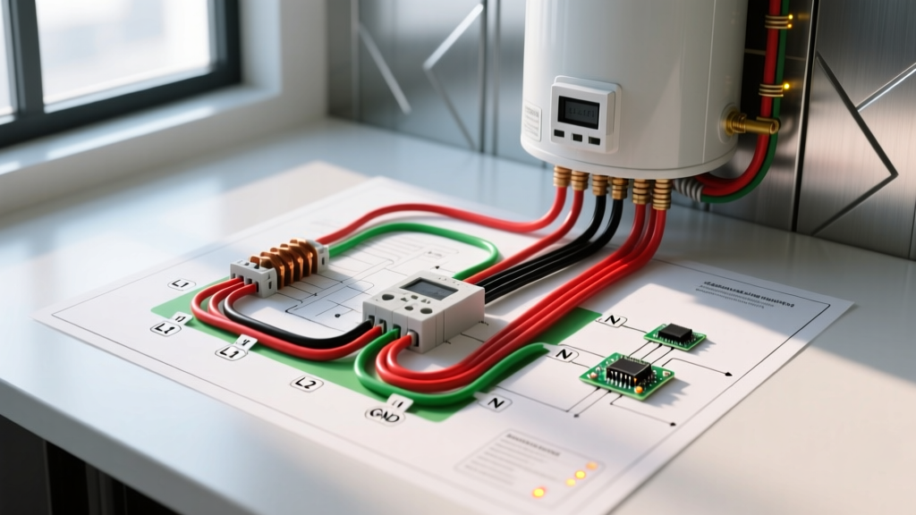
- Pictorial Diagrams: These show the physical layout of the components and the actual wire routing. They are color-coded and labeled with terminal designations (e.g., C, R, Y, W, G). Use the pictorial diagram to identify physical terminals, verify factory wire colors, and locate specific relays on a crowded control board.
- Ladder (Schematic) Diagrams: These represent the logical flow of electricity, ignoring physical layout. Power sources (L1 and L2) form the vertical "rails," while control and load circuits form the horizontal "rungs." Use the ladder diagram to understand the sequence of operations, identify safety interlocks (like high-pressure switches or thermal overloads), and trace the logical path of a 24VAC control signal.
Decoding the 24V Control Circuit
The low-voltage control circuit is the brain of the HVAC system. On your HVAC electrical wiring diagram, you will trace the 24VAC from the control transformer (usually rated at 40VA for modern systems) through the thermostat and back to the control board relays. A standard 5-wire thermostat setup uses:
- R (Red): 24VAC Hot
- C (Blue/Black): 24VAC Common
- Y (Yellow): Compressor Contactor Coil
- G (Green): Indoor Blower Fan Relay
- W (White): Heating Element or Gas Valve Relay
Step-by-Step Troubleshooting Scenarios
Scenario A: Condenser Unit Fails to Engage (High Voltage Side)
Symptom: The thermostat calls for cooling, the indoor blower starts, but the outdoor condenser remains completely silent.
Diagram Trace: Look at the ladder diagram for the outdoor unit. Trace L1 (240V) through the disconnect switch, into the contactor coil, and through the low-pressure and high-pressure safety switches to C (Common).
- Verify 240V at the Disconnect: Use a CAT III rated multimeter (like the Fieldpiece SC440) to measure across the two load-side lugs of the outdoor disconnect. You should read 240V (±10%).
- Check the Contactor Coil: Move to the control board. Measure across the Y and C terminals on the board's terminal strip. If you read 24VAC, the board is sending the signal. Next, measure across the actual contactor coil (A1 and A2). If you have 24VAC at the coil but the contactor does not pull in, the coil is open (failed). Replace the contactor.
- Inspect Safety Switches: If you have 24V at the board but 0V at the contactor coil, a safety switch is open. Use your multimeter in continuity mode (with power locked out) to test the high-pressure switch and the compressor internal thermal overload.
Scenario B: Blower Motor Runs Continuously (Low Voltage Side)
Symptom: The indoor blower fan will not turn off, even when the thermostat is set to "Off".
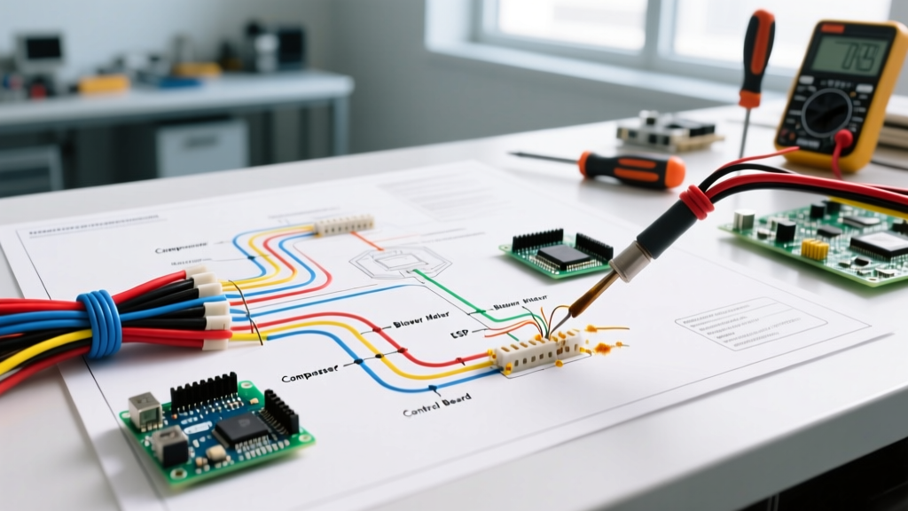
Diagram Trace: Consult the air handler schematic. The G wire from the thermostat energizes the fan relay. If the fan runs continuously, either the G wire is shorted to the R wire, or the fan relay on the control board is welded closed.
- Isolate the Thermostat: Remove the thermostat from the wall and disconnect the G wire. If the blower stops, the fault lies in the thermostat or the 18-gauge thermostat wire (likely a nicked wire causing an R-to-G short inside the wall).
- Test the Board Relay: If the G wire is disconnected at the board and the blower continues to run, the physical relay on the control board (e.g., a Honeywell ST9120U board) has mechanically failed and welded its internal contacts. The entire control board must be replaced.
Multimeter Diagnostic Matrix for HVAC Components
When using your HVAC electrical wiring diagram to isolate faults, reference this matrix for expected readings and failure modes.
| Component | Expected Reading (Normal) | Failure Mode Reading | Corrective Action |
|---|---|---|---|
| Dual Run Capacitor (e.g., 45/5 MFD) | 45µF (±6%) / 5µF (±6%) | Below 38µF or Open (OL) | Replace capacitor; check compressor amp draw for mechanical binding. |
| Contactor Coil (24VAC) | 15Ω to 40Ω resistance | Open (OL) or Short (0.0Ω) | Replace contactor; verify 24V transformer is not overloaded. |
| Control Board 3A Fuse | 0.0Ω (Continuity) | Open (OL) | Find short in 24V wiring (usually Y or G wire pinched) before replacing. |
| Compressor Windings (C to R, C to S) | R + S = C (e.g., 0.5 + 2.0 = 2.5Ω) | Short to ground or Open (OL) | Replace compressor; perform acid test on refrigerant oil. |
Advanced Diagnostics: ECM Motors and Ghost Voltages
Modern air handlers utilize Electronically Commutated Motors (ECMs), such as the Genteq X13 or GE ECM 3.0. Unlike standard PSC motors, ECMs have internal microprocessors. When troubleshooting an ECM using the wiring diagram, you are not just checking for voltage; you are checking for data signals.
If an ECM motor fails to spin, do not immediately condemn the motor. First, check the 5-pin harness from the control board. Pin 1 and 2 should provide 120VAC or 240VAC (depending on the model). Pins 3, 4, and 5 carry low-voltage DC signals dictating speed and torque profiles. If high voltage is present but the motor is dead, check the control module's thermistor. A failed thermistor will cause the module to shut down to prevent overheating.
The "Ghost Voltage" Trap
A common edge case in HVAC troubleshooting occurs when a technician reads 24VAC on the Y wire at the outdoor unit, but the contactor doesn't engage. This is often a "ghost voltage" caused by capacitive coupling in long runs of 18/5 thermostat wire. The induced voltage has high impedance and collapses under a real load. To eliminate this false diagnostic, switch your digital multimeter to LoZ (Low Impedance) mode. A LoZ reading will drop to near 0V if it is a ghost voltage, saving you from misdiagnosing a failed contactor coil.
Safety Protocols and 2026 A2L Standards
Electrical troubleshooting in HVAC carries severe risks, including arc flash and electrocution. Always adhere to Lockout/Tagout (LOTO) procedures before opening any electrical panel. Furthermore, when discharging a run or start capacitor, never use a flathead screwdriver across the terminals. This causes micro-fractures in the terminal spades and can lead to future arcing. Always use a 20,000-ohm, 5-watt wirewound resistor attached to insulated alligator clips to bleed the voltage safely.
2026 A2L Refrigerant Warning: With the phase-in of A2L refrigerants, electrical wiring diagrams now feature strict clearance requirements. According to updated safety standards, all potential ignition sources (including contactors and relays) must be sealed or located outside the refrigerant dispersion zone. Never bypass a factory-sealed electrical enclosure on an R-32 or R-454B system, as this violates fire codes and voids manufacturer warranties.
For comprehensive electrical safety standards and code compliance, technicians should regularly consult the NFPA 70 National Electrical Code (NEC), specifically Article 440 which covers air-conditioning and refrigerating equipment. Additionally, maintaining system efficiency and safe operation aligns with the U.S. Department of Energy HVAC Guidelines, which emphasize the importance of tight electrical connections to prevent voltage drops and component degradation. Finally, any work involving the refrigerant circuit alongside electrical diagnostics must comply with EPA Refrigerant Management Standards to ensure environmental and operational safety.
Conclusion
Mastering the HVAC electrical wiring diagram transforms a technician from a parts-changer into a true diagnostician. By systematically tracing the ladder logic, utilizing LoZ multimeter settings to eliminate ghost voltages, and understanding the specific failure modes of modern ECMs and A2L safety interlocks, you can accurately isolate faults on the first visit. Keep your schematics clean, your multimeter calibrated, and always prioritize electrical safety in the field.