
Decoding the EZGO Golf Cart Electric Wiring Diagram for 48V TXT Models
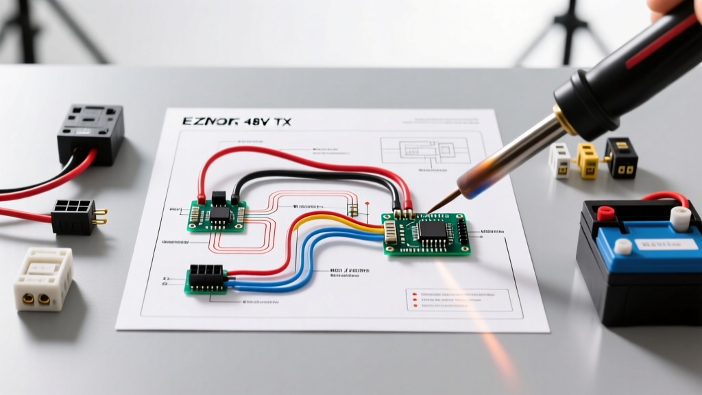
Whether you are upgrading a tired fleet cart or converting a gas model to electric, understanding the ezgo golf cart electric wiring diagram is the most critical step in your build. The EZGO TXT 48V platform (specifically the 1995–2013 series and DC motor configurations) remains the gold standard for DIY electric vehicle enthusiasts. As of 2026, the massive shift toward drop-in 48V lithium battery systems—such as the Eco Battery or Allied 48V—has made mastering this wiring diagram even more vital. Lithium Battery Management Systems (BMS) are highly sensitive to inductive voltage spikes and improper precharge circuits, meaning a wiring error that a lead-acid bank might tolerate will instantly trip a lithium BMS into protective shutdown.
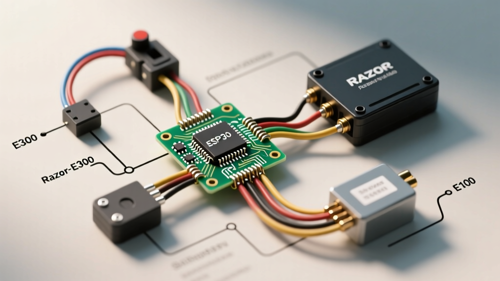
This step-by-step walkthrough focuses on the industry-standard Curtis 1268-4204 (or the modern Alltrax XCT 4834) controller paired with a standard DC series-wound motor. We will cover high-current routing, low-voltage logic circuits, and the critical inductive throttle system (ITS).
⚠️ CRITICAL SAFETY WARNING: A fully charged 48V nominal battery bank (especially lithium) can peak at 58.4V and deliver over 300 amps of continuous current. According to OSHA Battery Safety Guidelines, working on high-capacity DC systems requires insulated tools, ANSI-rated safety glasses, and removing all metallic jewelry. Always disconnect the main negative battery cable first and isolate it before beginning any wiring.Essential Components and Wire Gauge Specifications
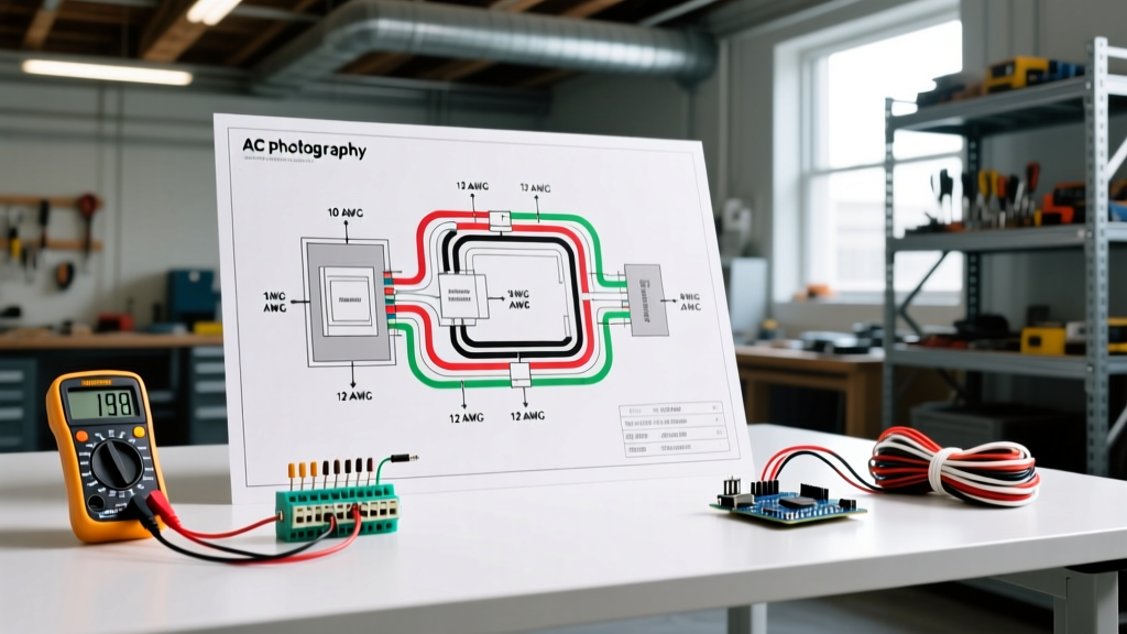
Before cutting a single wire, verify your materials. Using undersized wire on the high-current side leads to severe voltage drop, melted insulation, and controller failure. The National Fire Protection Association (NFPA) emphasizes that DC wiring requires strict adherence to ampacity charts due to the continuous nature of the load.
| Component | Function | Required Wire Gauge | Estimated 2026 Cost |
|---|---|---|---|
| Main Battery Cables | Battery to Controller (B+ / B-) | 2 AWG Welding Cable | $3.50 / ft |
| Motor Cables | Controller to Motor (A1, A2, D1, D2) | 2 AWG Welding Cable | $3.50 / ft |
| Heavy-Duty Solenoid | Main High-Current Contactors (48V) | 6 AWG to 2 AWG | $85.00 - $110.00 |
| Low-Voltage Harness | Key, F&R, Throttle, Reverse Buzzer | 16 AWG or 14 AWG Stranded | $0.45 / ft |
| Precharge Resistor | Prevents solenoid arcing & capacitor spike | 18 AWG (with 470Ω 5W Resistor) | $12.00 (Kit) |
Step 1: High-Voltage Main Power Routing
The high-voltage circuit carries the raw amperage from the battery bank to the motor controller. This is where the thickest cables are required.
1.1 Battery to Solenoid
Run a 2 AWG red cable from the main positive battery post to one of the large copper studs on your 48V solenoid. This stud is typically labeled Line or Battery.
1.2 Solenoid to Controller (B+)
Run a 2 AWG red cable from the opposite large stud on the solenoid (labeled Load or Motor) directly to the B+ (Main Positive) terminal on the Curtis or Alltrax controller. Pro-Tip: Use a 400A ANL fuse or marine-class MRBF terminal fuse on this specific cable run, placed within 7 inches of the battery positive terminal.
1.3 The Main Ground (B-)
Run a 2 AWG black cable from the main negative battery post directly to the B- (Main Negative) terminal on the controller. Do not ground the controller to the cart chassis. Golf carts are not grounded like automobiles; the controller must reference the battery negative directly to read shunt-based current draws accurately.
Step 2: Motor and Controller Integration
The EZGO TXT DC series-wound motor has four primary terminals: A1, A2 (Armature) and D1, D2 (Field/Stator). The controller dictates direction and speed by manipulating the polarity between the Armature and the Field.
- A1 (Armature 1): Connect to the controller's A1 terminal using 2 AWG wire.
- A2 (Armature 2): Connect to the controller's A2 terminal.
- D1 (Field 1): Connect to the controller's D1 terminal.
- D2 (Field 2): Connect to the controller's D2 terminal.
Edge Case Failure Mode: If you swap the A1/A2 wires, the motor will spin in the correct direction but will lack regenerative braking and torque. If you swap D1/D2, the cart will run in reverse when the F&R switch is set to forward. Always double-check factory stamped labels on the motor casing.
Step 3: The Solenoid and Precharge Circuit (Critical for Lithium)
The solenoid is a heavy-duty relay. When the low-voltage side is energized, it pulls a magnetic plunger to connect the high-voltage B+ to the controller. However, the controller contains massive internal capacitors. If the solenoid slams shut without a precharge circuit, the capacitors will draw a massive inrush current (often exceeding 1,000 amps for a millisecond). This will weld the solenoid contacts together, causing a dangerous "runaway cart" scenario, and will trip a lithium BMS into permanent fault mode.
Wiring the Precharge Resistor and Diode
- Locate the two small activation studs on top of the solenoid.
- Connect a 470-ohm, 5-watt ceramic resistor across the two large high-current studs (Line and Load).
- Wire a reverse-biased diode (e.g., 1N5408) in parallel with the resistor. The silver stripe on the diode must point toward the Load (controller) side. This allows the inductive spike from the motor to dissipate safely back into the battery bank when you release the throttle, protecting the controller's internal MOSFETs.
Step 4: Low-Voltage Control Circuit (The "Brain")
This circuit operates at pack voltage (48V-58V) but carries very low amperage (under 2A). It tells the controller when to wake up, which direction to spin, and how fast to go.
4.1 Key Switch and F&R (Forward and Reverse)
Run 16 AWG wire from the solenoid's Line stud (switched 48V) to the center terminal of the Key Switch. From the Key Switch output, run power to the center common terminal of the EZGO F&R Switch. The F&R switch routes power to either the Forward microswitch or the Reverse microswitch, which then feeds directly into the controller's logic pins (typically Pin 7 for Forward, Pin 8 for Reverse on a Curtis 1268).
4.2 The Inductive Throttle System (ITS)
Unlike older mechanical V-Glide resistors, the EZGO TXT uses an ITS throttle box. The ITS uses a Hall-effect sensor to send a variable voltage signal to the controller.
Expert Calibration Note: The EZGO ITS sweep operates between 0.9V (neutral/deadband) and 3.2V+ (full throttle). If your cart stutters off the line, use a digital multimeter to back-probe the ITS signal wire. If the resting voltage is below 0.8V or above 1.1V, the controller will trigger a High Pedal Disable (HPD) safety lockout. Adjust the physical potentiometer inside the throttle box until it reads exactly 0.95V at rest.
Step 5: Diagnostics and Edge-Case Troubleshooting Matrix
Even with a perfect wiring diagram execution, environmental factors and component aging introduce faults. Use this diagnostic matrix when the cart fails to operate.
| Symptom | Probable Cause | Multimeter Test & Fix |
|---|---|---|
| Cart is completely dead; no solenoid "click". | Blown main fuse, faulty key switch, or F&R switch misalignment. | Check for 48V+ at the Key Switch input. If 0V, check the main ANL fuse and battery interconnect cables. |
| Solenoid clicks, but motor does not spin. | Controller lockout (HPD), bad motor brushes, or open field coil. | Check ITS resting voltage (must be < 1.1V). Check continuity across D1 and D2 (should read 1-3 ohms). |
| Solenoid clicks rapidly ("machine gun" effect). | Severe voltage drop on the B- cable or failing solenoid coil. | Measure voltage drop across B- cable under load. If > 0.5V drop, replace the crimp lugs and 2 AWG cable. |
| Cart runs but has no regenerative braking or torque. | Armature and Field wires swapped at the controller. | Verify A1/A2 are on Armature, D1/D2 are on Field. Swap if necessary. |
Modern Upgrades and the Future of Cart Wiring
As noted by the Alternative Fuels Data Center, the transition to advanced lithium-ion and LiFePO4 chemistries in light electric vehicles has fundamentally changed how we approach DC wiring. When wiring a modern EZGO TXT with a lithium bank, always install a high-amp DC contactor rated for continuous DC loads, and ensure your controller's software is flashed to the specific lithium discharge curve. Standard lead-acid voltage sag profiles will cause a lithium cart to limp prematurely if the controller is not reprogrammed.
By following this exact ezgo golf cart electric wiring diagram walkthrough, verifying your wire gauges, and strictly adhering to the precharge and ITS calibration protocols, you will build a 48V system that is not only exceptionally fast but inherently safe and reliable for years to come.