
Decoding the Wiring Diagram for Kenwood Head Unit Models
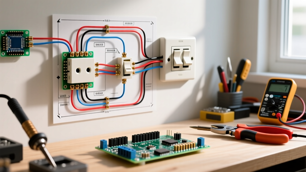
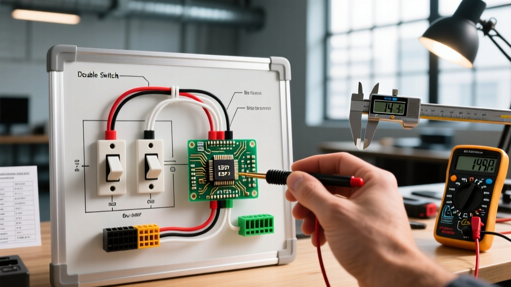
Upgrading your vehicle's audio system requires precision, patience, and a thorough understanding of the electrical architecture. When interpreting the wiring diagram for Kenwood head unit configurations—whether you are installing a flagship 2026 Excelon DNX9990HD or a reliable DMX709S digital media receiver—the margin for error is razor-thin. A miswired harness can lead to blown fuses, fried CAN bus networks, or parasitic battery drains. This comprehensive tutorial bridges the gap between the schematic in your Kenwood manual and the physical wires in your dashboard, ensuring a flawless, professional-grade installation.
Safety Warning: Never perform wiring modifications while the vehicle's battery is connected. Always disconnect the negative battery terminal and wait at least 10 minutes before cutting, stripping, or crimping any wires to prevent short-circuiting the SRS (airbag) or infotainment CAN bus modules.
The Standard 16-Pin Connector and CTA Color Codes
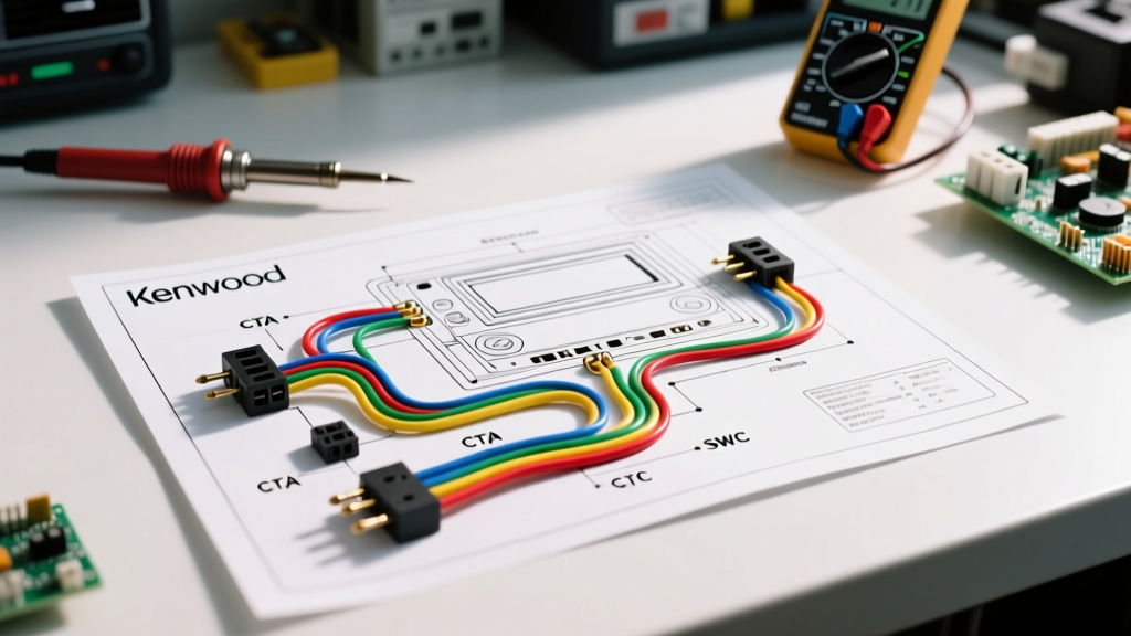
Kenwood adheres strictly to the Consumer Technology Association (CTA) standard for aftermarket car stereo wiring. This universal color-coding system, detailed by the CTA standards body, ensures that your head unit's harness will align predictably with standard vehicle adapter harnesses (such as those from Metra or Scosche). However, relying on memory rather than the specific wiring diagram for your exact Kenwood model can lead to costly mistakes, as illumination and amplifier turn-on wires occasionally vary between chassis generations.
Primary Power and Ground Matrix
The foundation of any stable car audio system lies in the power delivery network. Automotive environments are notoriously harsh, with voltage fluctuating between 11.5V (cranking) and 14.8V (alternator charging). Below is the critical power pinout you must verify on your Kenwood harness.
| Wire Color | Function | Destination / Connection Point | Wire Gauge & Protection |
|---|---|---|---|
| Yellow | 12V Constant (Memory) | Direct to battery or constant 12V fuse tap | 16 AWG (Min), 10A Inline Fuse |
| Red | 12V Switched (Ignition) | Ignition-controlled fuse tap or OEM radio harness | 18 AWG, 10A Inline Fuse |
| Black | Chassis Ground | Unpainted metal bolt on vehicle chassis | 16 AWG, Ring Terminal |
| Blue/White Stripe | System Remote Turn-On | Amplifier REM terminal or Power Antenna | 18 AWG, Max 300mA draw |
According to installation best practices outlined by the Crutchfield Learning Center, the yellow wire must be connected to a true constant 12V source. If you swap the red and yellow wires, the radio will turn on and off with the key, but it will wipe your presets, EQ settings, and paired Bluetooth devices every time you exit the vehicle.
Speaker Wire Pinouts and Phase Alignment
Kenwood's internal amplifier ICs (typically Toshiba or STMicroelectronics chips pushing 22W x 4 RMS) require precise phase alignment to prevent acoustic cancellation. The wiring diagram for Kenwood head unit speaker outputs utilizes a striped-wire convention to denote negative terminals.
- Front Left: White (Positive) / White with Black Stripe (Negative)
- Front Right: Gray (Positive) / Gray with Black Stripe (Negative)
- Rear Left: Green (Positive) / Green with Black Stripe (Negative)
- Rear Right: Purple (Positive) / Purple with Black Stripe (Negative)
Pro-Tip: Never ground the negative speaker wires to the vehicle chassis. Kenwood head units utilize BTL (Bridge-Tied Load) amplifier configurations. Grounding a negative speaker wire will instantly short-circuit and destroy the internal amplifier IC, voiding your warranty and requiring a mainboard replacement.
Integrating Steering Wheel Controls (SWC) and OEM Data
Modern vehicles rely on complex data networks to manage steering wheel buttons, backup cameras, and parking sensors. When consulting the wiring diagram for Kenwood head unit setups from 2024 through 2026, you will notice a distinct lack of hardwired SWC wires on the main 16-pin harness. Instead, Kenwood utilizes a dedicated 3.5mm male-to-male data jack on the rear chassis for SWC input, alongside a proprietary micro-USB port for advanced data retention modules like the iDatalink Maestro RR2.
Step-by-Step SWC Interface Wiring
- Identify the Vehicle Data Wires: Use a digital multimeter to locate the CAN High and CAN Low wires on the vehicle's OEM harness, or the analog SWC1/SWC2 resistive ladder wires on older models.
- Wire the Interface Module: Connect the vehicle data wires to your chosen interface (e.g., Axxess ASWC-1 or iDatalink Maestro). Do not connect these directly to the Kenwood harness.
- Connect the 3.5mm Jack: Route the 3.5mm male-to-male cable from the interface module's SWC output to the Kenwood's rear 3.5mm SWC input port.
- Program the Sequence: Power on the unit. The Kenwood firmware will prompt you to hold the 'Preset' buttons on your steering wheel to map the resistive voltage drops to specific software commands.
Bench Testing: The Professional's Secret
Before tucking wires into the dash cavity and securing the DIN cage, professional installers perform a bench test. This verifies the wiring diagram's accuracy and ensures the unit boots without throwing a DC offset or short-circuit error code. To do this, you need a regulated 12V DC power supply capable of delivering at least 5 amps (such as an Alinco DM-330MVT).
Connect the power supply's positive terminal to a fused distribution block. Run a jumper wire from the Kenwood's Yellow (Constant) wire to the positive block. Connect the Red (Switched) wire to the positive block via a momentary toggle switch. Finally, connect the Black (Ground) wire to the power supply's negative terminal. Power on the supply, flip the toggle switch, and verify that the Kenwood Excelon boot screen appears, the touchscreen digitizer responds, and the cooling fan engages silently. If the unit displays a 'PROTECT' warning, immediately cut power and inspect your speaker wires for pinched insulation.
Troubleshooting Real-World Failure Modes
Even with the correct wiring diagram for Kenwood head unit installations, environmental factors and OEM quirks can introduce anomalies. Below is a diagnostic matrix for the most common post-installation issues.
| Symptom | Probable Cause | Diagnostic & Resolution |
|---|---|---|
| Alternator Whine (Pitch changes with RPM) | Ground Loop or Pinched RCA Cables | Ensure head unit ground and amplifier ground share the exact same chassis bolt. Check RCA cables for crushed shielding near the center console. |
| Unit turns on, but no audio output | Blue/White wire not connected to Amp REM | Verify the Blue/White stripe wire (not the solid Blue power antenna wire) is triggering the external amplifier's remote terminal. |
| Parasitic Battery Drain (Car won't start) | Red and Yellow wires swapped or CAN bus awake | Test current draw with multimeter in series with battery negative. If draw exceeds 50mA with key off, verify Red is on switched ignition, not constant. |
| Backup Camera displays 'No Signal' | Missing Reverse Trigger Wire | Connect the vehicle's reverse light 12V+ wire to the Kenwood harness's Purple/White stripe wire to trigger the video input relay. |
Termination Techniques: Crimping vs. Soldering
When mating the Kenwood pigtail to your vehicle-specific adapter harness, the termination method dictates the longevity of the install. While soldering provides a low-resistance bond, it can become brittle under the constant vibration of a vehicle chassis, leading to micro-fractures and intermittent audio dropouts.
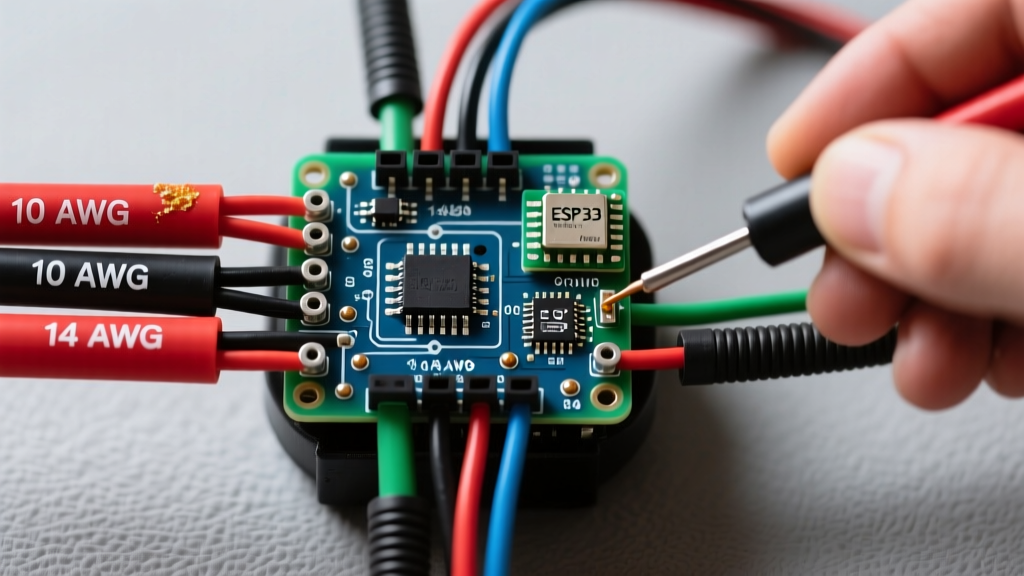
For 2026 automotive standards, the preferred method is using nylon-insulated, heat-seal butt connectors. Strip exactly 5/16th of an inch of insulation from both the Kenwood 18 AWG wire and the adapter harness wire. Insert them into a high-quality crimp barrel (such as those from Knipex or Glarks) and compress using a ratcheting crimper. Finally, apply heat with a precision heat gun until the internal adhesive sealant melts and oozes slightly from the ends. This creates a waterproof, vibration-proof seal that prevents copper oxidation and ensures the electrical integrity of your Kenwood head unit for the life of the vehicle.
By treating the wiring diagram for Kenwood head unit systems not just as a suggestion, but as a strict electrical blueprint, you eliminate the guesswork from car audio integration. Proper gauge selection, meticulous termination, and rigorous bench testing transform a frustrating weekend project into a seamless, factory-quality upgrade.
For further reading on automotive electrical safety and advanced integration techniques, consult the official Kenwood Electronics Support Portal for model-specific PDF schematics and firmware update logs.