
The Safety Imperative in Radiator Fan Relay Circuits
When modifying or repairing an automotive cooling system, the wiring diagram for radiator fan relay setups is often treated as an afterthought. This is a critical mistake. High-draw cooling fans, such as the popular Spal 30102804 (drawing up to 25A on startup), generate immense thermal and electrical stress. Bypassing relays, using undersized wire gauges, or ignoring flyback voltage protection are leading causes of engine bay fires and melted wiring harnesses.
As of 2026, with the surge in EV conversions and custom restomods utilizing electric water pumps and high-CFM puller fans, adhering to strict electrical codes is non-negotiable. While traditional internal combustion engine (ICE) vehicles follow SAE J1128 standards for low-tension automotive wire, custom builds and EV swaps must also cross-reference NFPA 70 (National Electrical Code) Article 511 for commercial garages and custom vehicle compliance. This guide provides a master-level, code-compliant approach to wiring your radiator fan relay safely.
Anatomy of a Compliant 5-Pin Relay Circuit
The industry standard for high-amperage automotive switching is the ISO 7588-1 / DIN 72552 5-pin relay (commonly referred to as a Bosch-style relay). A premium example is the Bosch 0332014150 or equivalent Littelfuse automotive relays, typically priced between $6 and $14. These relays isolate the high-current load circuit from the low-current control circuit.
⚠️ SAE & IPC Crimping Compliance Warning
Never use twist-and-tape connections or solder-only joints in high-vibration, high-heat engine bays. Solder becomes brittle under thermal cycling. All connections must utilize open-barrel or closed-barrel crimps meeting IPC/WHMA-A-620 standards, sealed with dual-wall heat shrink tubing containing polyamide adhesive to prevent moisture ingress and galvanic corrosion.
Understanding the DIN Pinout
- Pin 30 (Common / Power In): Receives fused 12V/14.4V power directly from the battery or main distribution bus.
- Pin 87 (Normally Open / Load Out): Sends power to the radiator fan positive terminal when the relay coil is energized.
- Pin 87a (Normally Closed): Leave this pin empty and insulated in fan circuits. Using 87a for secondary accessories can cause dangerous backfeed voltages when the coil de-energizes.
- Pin 86 (Coil Positive): Receives the trigger signal from the thermostat switch, ECU, or ignition-switched source.
- Pin 85 (Coil Negative): Connects to a clean chassis ground or the ECU's low-side driver.
Step-by-Step Wiring Diagram Execution
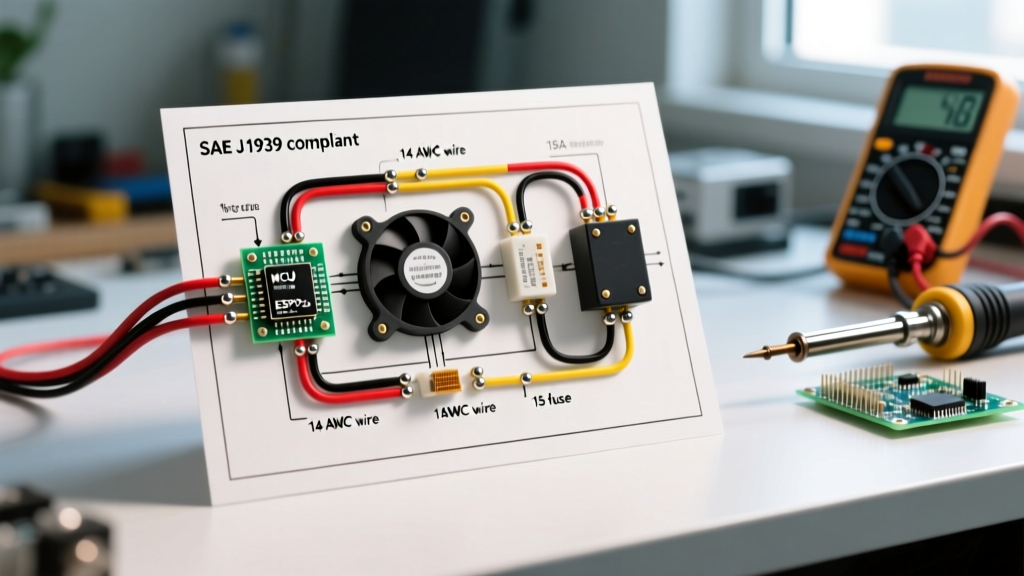
To ensure optimal voltage delivery and compliance with safety standards, follow this sequential wiring protocol. Voltage drop across the high-current circuit must not exceed 3% (approx. 0.4V on a 14.4V charging system).
Step 1: The High-Current Load Circuit (Pins 30 & 87)
- Battery to Fuse: Run 10 AWG TXL (cross-linked polyethylene) wire from the battery positive terminal to a fuse holder mounted within 7 inches of the battery. This complies with marine and ABYC/NFPA safety mandates for unprotected wire length.
- Fuse to Relay Pin 30: Continue the 10 AWG wire to Pin 30 on the relay harness.
- Relay Pin 87 to Fan: Run 10 AWG wire from Pin 87 to the positive terminal of the radiator fan. If using dual fans wired in parallel, upgrade to 8 AWG for the main trunk line, splitting to 10 AWG at a sealed distribution block.
- Fan Grounding: Ground the fan negative directly to the chassis or engine block using a 10 AWG ring terminal. Scrape away all paint and clear coat to bare metal, secure with a star washer and stainless steel bolt, and coat with dielectric grease.
Step 2: The Low-Current Control Circuit (Pins 85 & 86)
- Trigger Source to Pin 86: Use 14 AWG or 16 AWG wire from your ignition-switched source or ECU fan-control output to Pin 86.
- Pin 85 to Ground/Switch: If using a mechanical thermostat switch (e.g., Hayden 3653 mounted in the radiator fins), route Pin 85 to the switch, and the switch to ground. If controlled by an ECU, route Pin 85 to the ECU's dedicated low-side ground pin.
Step 3: Flyback Diode Installation (Critical for ECU Safety)
When the relay coil de-energizes, the collapsing magnetic field generates a high-voltage spike (flyback voltage) that can destroy sensitive ECU drivers or digital dash clusters. Solder a 1N4004 rectifier diode across Pins 85 and 86. The diode's cathode (silver stripe) must point toward Pin 86 (Positive). This creates a safe recirculation loop for the inductive spike.
Wire Gauge, Fuse Sizing, and Run Length Matrix
Sizing your overcurrent protection and wire gauge correctly is dictated by the continuous amperage draw of your specific fan setup. According to NEC and SAE guidelines for continuous loads (running 3 hours or more, common in heavy traffic or track use), fuses must be rated at 125% of the continuous draw.
| Fan Continuous Draw | Min. Wire Gauge (TXL) | Required Fuse Rating (125%) | Max Run Length (One Way) |
|---|---|---|---|
| 10A - 15A | 14 AWG | 20A ATO | 12 Feet |
| 16A - 20A | 12 AWG | 25A ATO | 10 Feet |
| 21A - 30A | 10 AWG | 35A or 40A ATO/MAXI | 8 Feet |
| 31A - 50A (Dual Fans) | 8 AWG | 60A MAXI / MIDI | 6 Feet |
Modern 2026 Edge Cases: PWM Fan Controllers
In modern restomods and EV conversions, simple on/off relays are being replaced by Pulse Width Modulation (PWM) fan controllers (e.g., Holley Terminator X PWM modules or Davies, Craig digital controllers). These devices ramp fan speed from 30% to 100% based on coolant temperature, drastically reducing alternator load and electrical noise.
Wiring Shift: When using a PWM controller, the heavy-duty relay is often eliminated or replaced by a high-amperage solid-state relay (SSR) or integrated MOSFET within the controller itself. However, the heavy-gauge wiring rules (10 AWG / 8 AWG) and chassis grounding protocols remain identical. Ensure your PWM controller is rated for at least 1.5x the stall current of your fan motor to prevent thermal shutdown of the MOSFETs.
Common Failure Modes & Troubleshooting
- Relay Chatter / Rapid Clicking: Usually caused by a voltage drop in the control circuit (Pin 86) due to undersized wire or a poor ignition switch connection. The relay coil requires a minimum of 10.5V to latch securely. Test with a multimeter under load.
- Melted Relay Socket: Cheap, off-shore relay sockets use thin brass contacts that increase resistance, generating heat (I²R losses). Always use ceramic-filled or high-temp nylon sockets with thick copper-alloy terminals. Replace any socket showing brown heat marks immediately.
- Fan Runs After Engine Off: A classic symptom of wiring Pin 87 and 30 backward on certain OEM harnesses, or a failed ECU low-side driver holding Pin 85 to ground. Install a secondary manual override toggle switch on the dashboard wired in parallel with the thermostat switch for emergency track use.
Expert FAQ: Compliance & Best Practices
Can I use a standard 30A relay for a fan that pulls 25A?
While a 30A relay (like the standard Bosch 4-pin) is technically rated for the continuous load, the inrush (stall) current of a 25A fan can momentarily spike to 45A. This causes micro-welding on the relay's internal contacts over time. For any fan drawing over 20A continuous, upgrade to a 40A or 50A heavy-duty relay (e.g., Hella 4RD 933 332) to ensure longevity and prevent contact welding.
Do I need to fuse the control circuit (Pins 85/86)?
Yes. Code compliance dictates that any wire smaller than the main circuit breaker/fuse must have its own localized protection. Since the control circuit uses 14 AWG or 16 AWG wire, it must be protected by a 5A or 7.5A inline fuse near the tap-in point to prevent a short from melting the control harness.
Is it safe to ground the relay coil to the radiator support?
No. Radiator supports are often bolted through rubber isolators or painted, creating high-resistance ground paths. Always run the relay coil ground (Pin 85) back to the engine block or a dedicated, bare-metal grounding bus bar tied directly to the battery negative terminal via a minimum 4 AWG ground strap.