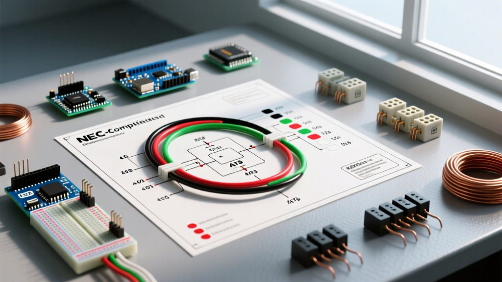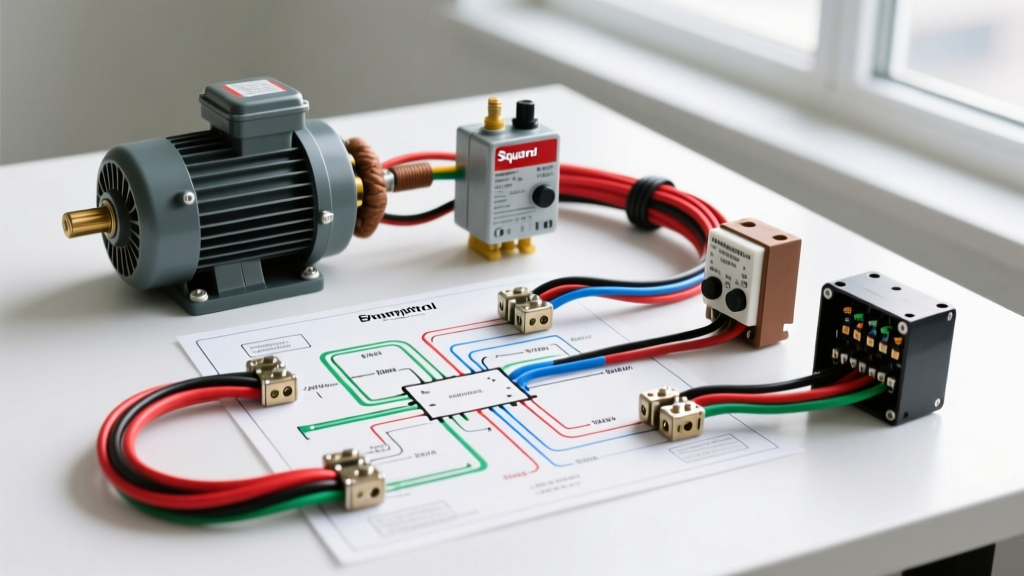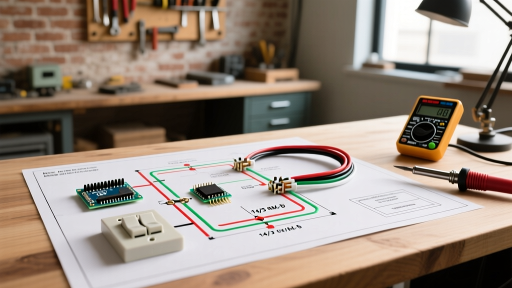

The Nomenclature Divide: 2-Way (IEC) vs. 3-Way (NEC)
Before pulling a single foot of wire, professional electricians must address a critical terminology split. In North America, the National Electrical Code (NEC) refers to a switch that controls a single load from two separate locations as a 3-way switch. However, under IEC standards and in the UK, Australia, and most of the world, this exact same configuration is known as a 2-way switch. (Conversely, what the US calls a standard single-pole switch is known internationally as a 1-way switch).
This installation planning guide uses the international "2-way" terminology to match our target keyword, but applies strict US NEC (2023/2026 edition) installation codes, box fill calculations, and wire gauge requirements. Whether you are roughing in a new stairwell lighting circuit or retrofitting a hallway, mastering the wiring diagram for a 2 way switch requires meticulous pre-installation planning.
Phase 1: Load Calculation and Wire Gauge Selection
The foundation of any switching circuit is the breaker size and the corresponding wire gauge. For standard residential LED and incandescent lighting circuits, you will typically be working with a 15-Amp or 20-Amp branch circuit.
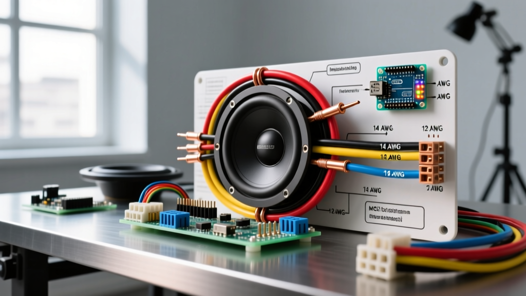
- 15-Amp Circuit: Requires 14 AWG copper wire. You will need 14/2 NM-B (Non-Metallic Sheathed Cable) for the line and load runs, and 14/3 NM-B for the traveler run between the two switch boxes.
- 20-Amp Circuit: Requires 12 AWG copper wire. You will need 12/2 NM-B for line/load and 12/3 NM-B for the travelers.
Pro-Tip for 2026 Smart Homes: Even if your lighting load is minimal, many master electricians now pull 12/3 NM-B for all 2-way switch circuits. The marginal material cost increase (roughly $0.15 per foot) provides the physical durability and thermal headroom required for modern smart switches, which often draw standby power and generate localized heat.
Phase 2: NEC Box Fill Calculations
One of the most common failures in DIY and junior-level electrical work is overcrowding the junction box. According to NFPA NEC Article 314, every box must have adequate cubic inch capacity based on the number and size of conductors, devices, and clamps.
When planning your wiring diagram for a 2 way switch, use this reference table to ensure your selected electrical boxes meet code:
| Component Type | 14 AWG Allowance | 12 AWG Allowance |
|---|---|---|
| Each Current-Carrying Conductor | 2.0 cu in | 2.25 cu in |
| All Equipment Grounding Wires (Combined) | 2.0 cu in | 2.25 cu in |
| Internal Cable Clamps (Combined) | 2.0 cu in | 2.25 cu in |
| Each Switch or Receptacle Device | 4.0 cu in (counts as 2) | 4.5 cu in (counts as 2) |
Real-World Box Fill Example
Imagine Switch Box #1 receives the line voltage (14/2) and sends the travelers to Switch Box #2 (14/3). Let us calculate the required box volume for 14 AWG:
- Conductors: 5 current-carrying wires (Line Hot, Line Neutral, Traveler 1, Traveler 2, Traveler Neutral re-identified) = 10.0 cu in.
- Grounds: 1 allowance for all bare copper grounds = 2.0 cu in.
- Device: 1 standard toggle switch = 4.0 cu in.
- Total Required: 16.0 cubic inches.
A standard "old work" single-gang plastic box typically offers 18 to 22 cubic inches, which passes inspection. However, if you are installing a bulky smart switch or adding a pass-through neutral for a downstream receptacle, you must upgrade to a deep single-gang box (22.5 cu in) or a single-gang masonry box.
Phase 3: Mapping the Wiring Diagram for a 2 Way Switch
There are multiple ways to physically route a 2-way (3-way) circuit depending on where the power source enters the system. The most common and easiest to troubleshoot is the Line-to-Switch-1-to-Switch-2-to-Load topology.
Step-by-Step Routing Logic
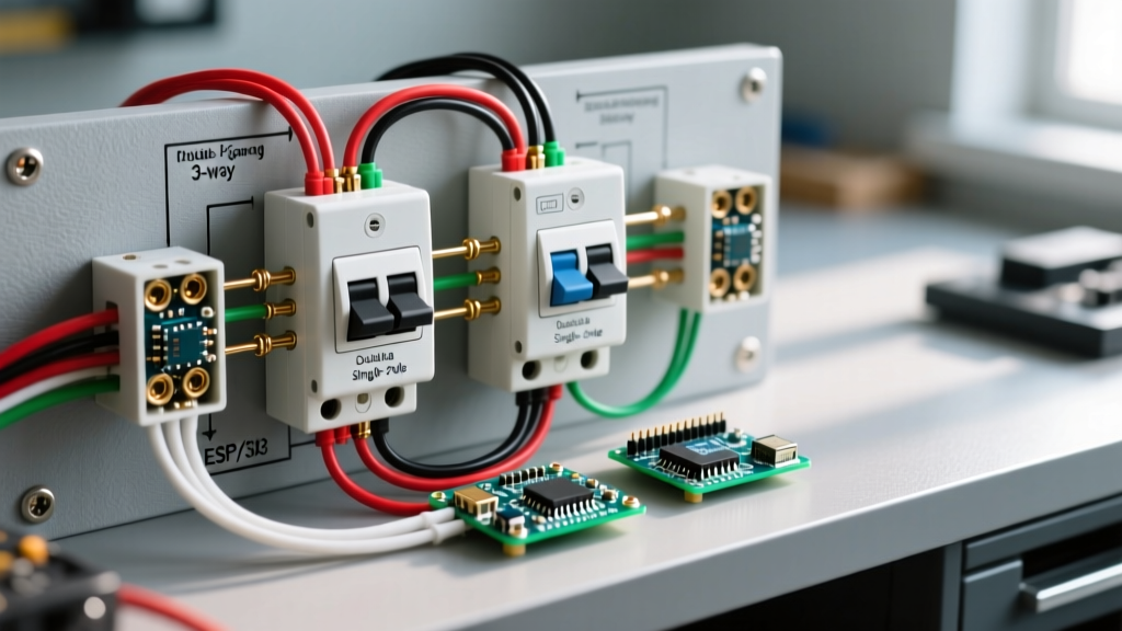
- Power Source to Switch 1: Run 14/2 NM-B from the breaker panel to the first switch box. The black (hot) wire connects to the Common (usually dark-colored) terminal on Switch 1. The white (neutral) wire splices directly to the load's neutral using a Wago 221 or standard wire nut.
- Switch 1 to Switch 2 (The Travelers): Run 14/3 NM-B between the two switch boxes. The black and red wires connect to the Traveler (brass-colored) terminals on Switch 1. The white wire in this 14/3 cable is re-identified with black electrical tape at both ends and acts as the switched hot or common feed to Switch 2.
- Switch 2 to the Load: At Switch 2, the re-identified white wire from the 14/3 cable connects to the Common terminal. The black and red traveler wires connect to the brass traveler terminals. Finally, run 14/2 NM-B from Switch 2 to the light fixture. The black wire from this final 14/2 run is spliced to the re-identified white traveler wire (or routed via the common terminal, depending on exact diagram variant).
Edge Cases and Pre-Wiring Pitfalls
When reviewing a standard wiring diagram for a 2 way switch, planners often overlook modern edge cases that can derail an installation on drywall day.
The "Missing Neutral" Problem in Smart Switches
If you plan to install smart switches (like the Leviton Decora Smart line or Lutron Caseta), the traditional traveler wiring diagram changes drastically. Most modern smart switches require a neutral wire at the switch box to power the internal Wi-Fi/Zigbee radio. In older homes, or in poorly planned new builds, the switch loop only contains hot and switched-hot wires. Always plan to pull a neutral to both switch boxes in a 2-way circuit to future-proof for smart home upgrades.
Shared Neutrals and AFCI/GFCI Tripping
Under current NEC guidelines enforced by OSHA and local AHJs (Authority Having Jurisdiction), most bedroom and living area lighting circuits require AFCI (Arc-Fault Circuit Interrupter) protection. If you share a neutral wire between a 2-way lighting circuit and a separate receptacle circuit on a different breaker, the AFCI breaker will detect an imbalance and trip immediately. Keep the 2-way switch circuit's neutral entirely isolated and dedicated to its own breaker.
Essential Tools for the Pull and Termination
Executing the physical installation requires more than just linemans pliers. Ensure your tool kit includes:
- Klein Tools 11063W Wire Stripper: Essential for cleanly stripping 14 and 12 AWG without nicking the copper, which creates a hot spot and potential arc-fault.
- Ideal Industries Wire-Nut Tan (Tan #14 or Red #33): For secure splicing of 3 to 4 wires in the junction box.
- Fluke T+PRO Electrical Tester: To verify the absence of voltage and test for continuity across the travelers before energizing the circuit.
- Green Nylon Pull String: If pulling through EMT conduit rather than using NM-B cable, always leave a pull string in the conduit for future upgrades.
Frequently Asked Questions (FAQ)
Can I use 14/2 wire instead of 14/3 for the travelers?
No. A traditional mechanical 2-way (3-way) switch requires two distinct traveler wires to pass the alternating hot state between the two switches. Using 14/2 will leave you one wire short. The only exception is if you are using a specialized wireless smart switch system (like Lutron Pico remotes), which eliminates the need for physical traveler wires entirely.
Does it matter which traveler terminal I use on the switch?
On standard mechanical switches, the two brass traveler terminals are interchangeable. Swapping the red and black traveler wires will not affect the operation of the circuit. However, the Common (dark/black) terminal must strictly receive the line hot or the load feed.
What is the maximum distance I can run 14 AWG wire for this circuit?
To maintain a voltage drop of less than 3% on a 15-Amp, 120-Volt circuit, the maximum one-way distance from the breaker to the furthest load is approximately 50 feet. If your stairwell or long hallway exceeds this distance, you must upgrade to 12 AWG wire and a 20-Amp breaker.