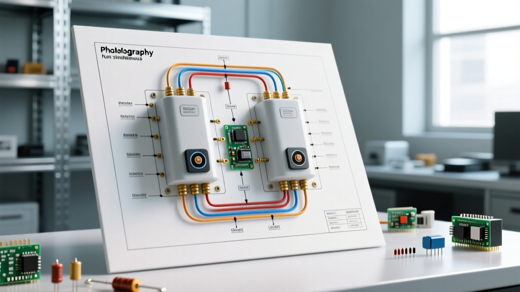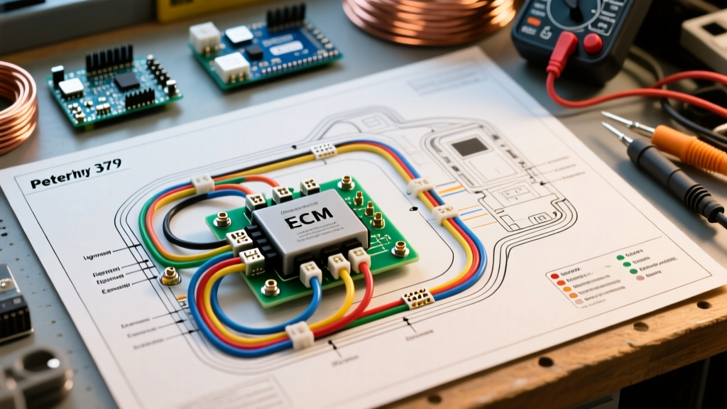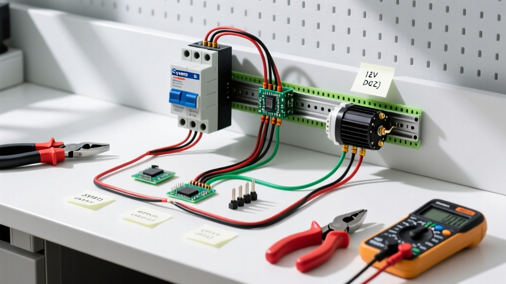

Mastering the Wiring Diagram for Pressure Switch Motor Control
Air compressors, shallow well pumps, and HVAC systems rely on pressure switches to act as the brain of the motor control circuit. When wiring a 120V or 240V single-phase motor, misinterpreting the wiring diagram for pressure switch terminals can lead to catastrophic contact welding, motor burnout, or severe electrical shock. In this comprehensive motor wiring tutorial, we break down the exact schematic logic, terminal designations, and physical wiring procedures for industry-standard switches like the Square D 9013FSG2 and Condor MDR3.
Anatomy of a Motor Pressure Switch
Before touching a wire stripper, you must understand the internal mechanics of the switch. A standard diaphragm-actuated pressure switch contains a normally closed (NC) electrical contact block. As system pressure drops to the 'cut-in' threshold, the spring tension overcomes the diaphragm pressure, snapping the contacts closed to energize the motor. When the system reaches the 'cut-out' pressure, the diaphragm pushes against the spring, opening the contacts and killing power to the motor.
Crucial Line vs. Load Designation
The most common mistake DIYers make is ignoring Line (L1/L2) and Load (T1/T2) designations. While a basic single-phase AC switch will technically operate if wired backward, reversing the line and load leaves the internal switching mechanism energized even when the motor is off. This creates a lethal shock hazard during future maintenance. Always wire the incoming power source to the Line terminals and the motor leads to the Load terminals.
Component Comparison: Square D vs. Condor
Choosing the right switch dictates your wiring approach, particularly regarding thermal overload integration and unloader valve actuation.
| Feature | Square D 9013FSG2 (Standard) | Condor MDR3 (Industrial) |
|---|---|---|
| Max HP Rating | 2 HP @ 120V / 3 HP @ 240V | 3 HP @ 120V / 5.4 HP @ 240V |
| Thermal Overload | None (Requires external relay) | Integrated adjustable dial |
| Unloader Mechanism | Mechanical brass valve (1/4" NPT) | Mechanical with optional electronic |
| Terminal Type | Box lug with pressure plate | Screw terminal with clamping plate |
Step-by-Step Wiring Procedure
Follow this exact sequence to ensure a safe, code-compliant installation. Always verify power is disconnected at the main breaker panel before beginning.
Step 1: Prepare the Conductors
Strip exactly 3/4-inch of insulation from the incoming Line and Load wires. Stripping too little leaves insulation under the pressure plate, causing high-resistance hot spots. Stripping too much exposes bare copper outside the terminal block, creating a short-circuit risk. Use a torque screwdriver to tighten the terminal screws to 14 in-lbs to prevent vibration-induced loosening.
Step 2: Wire the Line Side (Incoming Power)
- Route your incoming 2-wire (plus ground) or 3-wire (plus ground) cable through the left-side knockout.
- Connect the incoming Hot (Black) to L1.
- Connect the incoming Hot (Red or White-taped-black for 240V) to L2.
- Connect the bare/green ground wire directly to the green grounding screw on the switch metal chassis. Never use the pressure switch casing as a ground path without a dedicated bonding wire.
Step 3: Wire the Load Side (Motor Connection)
- Route the motor whip through the right-side knockout.
- Connect Motor Lead T4 (or Black) to T1.
- Connect Motor Lead T5 (or Red) to T2.
- Bond the motor ground to the switch chassis ground screw using a pigtail.
Step 4: Integrate the Unloader Valve (Compressors Only)
For air compressors, the unloader valve bleeds trapped air from the pump head when the motor stops, allowing the motor to restart under no-load conditions. Thread the mechanical unloader valve into the 1/4" NPT port on the bottom of the Square D switch. Use two wraps of PTFE tape and torque to 15 ft-lbs. If the unloader fails to vent, the motor will stall, draw locked-rotor amperage (LRA), and trip the breaker.
Wire Gauge & Breaker Sizing Matrix
Sizing your wire and breaker correctly is governed by NFPA 70 (National Electrical Code) Article 430. Motors draw massive inrush currents (up to 600% of Full Load Amps) during startup. Standard branch circuit sizing rules do not apply.
| Motor HP | Voltage | Approx. FLA | Min Copper Wire (THHN) | Max Inverse Time Breaker (NEC 430.52) |
|---|---|---|---|---|
| 1.0 HP | 120V | 16A | 12 AWG | 40A |
| 1.5 HP | 120V | 20A | 10 AWG | 50A |
| 2.0 HP | 240V | 12A | 12 AWG | 30A |
| 3.0 HP | 240V | 17A | 10 AWG | 45A |
| 5.0 HP | 240V | 28A | 8 AWG | 70A |
Note: While the NEC allows large breakers to accommodate startup surges, the motor's internal thermal overload protector or an external overload relay must be sized precisely to the motor's FLA to prevent winding burnout.
2026 Code Updates: GFCI and AFCI Requirements
As of the latest NEC adoption cycles rolling out through 2026, ground-fault circuit interrupter (GFCI) requirements have expanded significantly. If your pressure switch controls a 120V or 240V single-phase motor located in a garage, basement, or outdoor enclosure, the branch circuit must be GFCI protected. For hardwired compressors or well pumps, this means installing a 2-pole GFCI breaker in the main panel, as standard receptacle GFCIs are not rated for the high inrush currents of direct-wired motors. Always consult your local AHJ (Authority Having Jurisdiction) for specific regional amendments.
Advanced Troubleshooting & Failure Modes
Even with a perfect wiring diagram for pressure switch execution, components degrade. Here is how to diagnose the three most common field failures:
1. Contact Welding (Motor Won't Stop)
Symptom: The motor continues to run past the cut-out pressure, forcing the safety relief valve to blow.
Cause: Inductive kickback from the motor has caused micro-arcing across the contacts. Over time, the brass contacts pit and eventually weld shut.
Fix: Replace the switch immediately. Do not attempt to file the contacts, as this removes the silver-cadmium oxide plating designed to resist arcing. Install an RC snubber network across the load terminals to suppress future voltage spikes.
2. Diaphragm Rupture (Motor Won't Start)
Symptom: Pressure drops to zero, but the motor remains off. Manually pushing the contact lever starts the motor.
Cause: The internal rubber diaphragm has fatigued and torn, failing to transfer air pressure to the mechanical actuator.
Fix: Replace the entire switch assembly. Diaphragm repair kits are rarely cost-effective for switches under $50.
3. Unloader Valve Chatter
Symptom: A rapid 'machine-gun' clicking sound occurs immediately after the motor shuts off.
Cause: The O-ring inside the unloader valve seat is degraded, or the pilot pin is fouled with carbon buildup.
Fix: Depressurize the tank completely. Disassemble the brass unloader valve, clean the pilot pin with brake cleaner, and replace the O-ring with a standard Buna-N sizing kit.
Safety and Compliance Reminders
Working with motor control circuits requires strict adherence to safety protocols. According to OSHA Electrical Safety Standards, all lockout/tagout (LOTO) procedures must be verified with a CAT III or CAT IV multimeter before touching any terminal. Furthermore, for agricultural or rural well pump setups, ensuring proper grounding rod integration is critical to prevent stray voltage issues, a topic extensively covered by Penn State Extension Water Systems research.
Pro Tip: Always leave a 1-inch service loop of wire inside the pressure switch enclosure. When you inevitably need to replace the switch 5 years from now, that extra wire will save you from having to pull a brand-new cable through the conduit.
By strictly following this wiring diagram for pressure switch configurations and respecting the electrical tolerances of your specific motor, you will ensure a reliable, safe, and long-lasting installation.