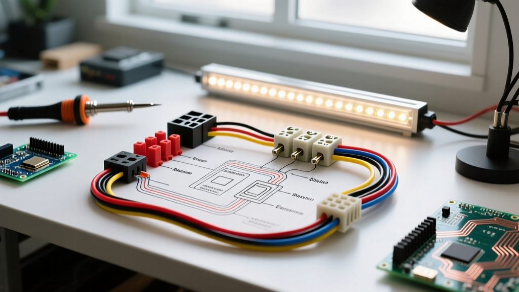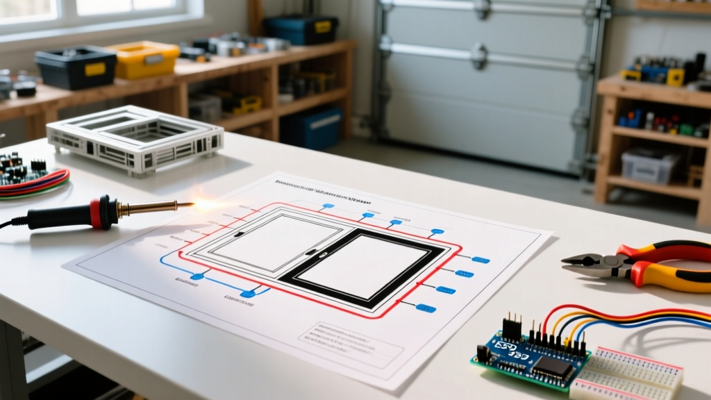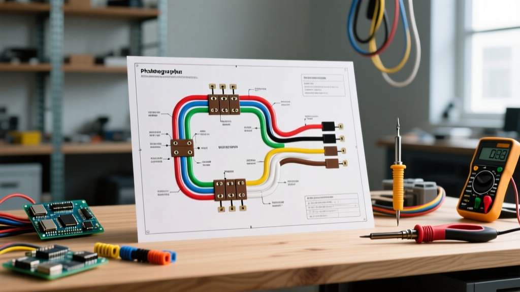

Introduction to the John Deere L110 Electrical Architecture
When diagnosing a no-crank, no-charge, or PTO engagement failure, having a clear understanding of the wiring diagram for John Deere L110 tractors is essential. Produced between 2002 and 2005, the L110 is powered by a 17HP Kohler Courage SV590S engine and utilizes a traditional 12-volt DC electrical system. Unlike modern equipment that relies on complex CAN-bus networks, the L110 uses a point-to-point copper wiring harness. While this makes the system highly serviceable for DIYers, the 20-year-old harnesses are now highly susceptible to vibration-induced chafing, brittle insulation, and Weather-Pack connector corrosion.
This step-by-step walkthrough breaks down the primary circuits, providing exact multimeter testing points, wire gauge specifications, and real-world failure modes to help you trace faults efficiently.
Preparation and Safety Protocols
Before probing any connectors, you must isolate the power source to prevent accidental short circuits or starter engagement.
- Power Isolation: Disconnect the negative (black) cable from the Group U1 12V battery. Secure the cable away from the terminal.
- Required Tools: Digital Multimeter (DMM) with continuity and min/max recording, wire piercers, terminal release picks, and heat shrink tubing.
- Reference Documentation: Always cross-reference your physical harness with the specific Technical Manual (TM) for your serial number break, as mid-year production changes can alter switch pinouts.
Step 1: Tracing the Starting Circuit
The starting circuit on the L110 is heavily integrated with the safety interlock system. Power originates from the positive battery terminal via a heavy 10 AWG red cable routed directly to the starter solenoid's main battery lug.
The Ignition Switch Logic
The 5-terminal ignition switch (typically John Deere part #AM133059 or AM107367) acts as the primary gateway for the 12V control circuits. When you turn the key to the START position, the following sequence occurs:
- 12V DC enters the switch at the B (Battery) terminal via a 12 AWG red wire.
- The internal wiper bridges the B terminal to the S (Start) terminal.
- 12V exits the S terminal on a 16 AWG purple wire, heading toward the safety interlock relays and brake switch.
- If the brake pedal is fully depressed and the PTO is disengaged, the 12V signal successfully reaches the starter solenoid's trigger spade (usually a white or purple wire depending on the exact harness revision).
Expert Insight: If you hear a single 'click' from the solenoid but the starter doesn't turn, do not immediately replace the starter. Use your DMM to check voltage at the solenoid trigger terminal while an assistant holds the key in START. If you read less than 10.5V, you have a voltage drop across a corroded safety switch or a failing ignition switch, not a bad starter motor.
Step 2: Decoding the Safety Interlock System
The L110 employs a series of normally-open (NO) and normally-closed (NC) switches to prevent the engine from cranking in gear or starting with the mower blades engaged.
- Brake Pedal Switch: Must be closed (circuit complete) for the starter solenoid to receive the 12V trigger signal.
- PTO Engagement Switch: Must be in the OFF position. If the PTO is pulled ON, the interlock module interrupts the start signal.
- Seat Switch: Primarily monitors operator presence during operation. If the operator leaves the seat while the PTO is engaged, the TCU (Transmission Control Unit) or interlock relay grounds the ignition module, killing the engine instantly.
Failure Mode: The wiring harness routing near the steering column is a notorious failure point on the L110. The harness rubs against the raw metal edge of the steering shaft bracket. Over time, the 16 AWG interlock wires chafe, exposing copper and causing a direct short to the chassis. This instantly blows the main 20A inline fuse and results in a complete loss of electrical power.
Step 3: PTO Clutch Engagement and Diagnostics
The electric PTO clutch (often manufactured by Warner Electric or Ogura) requires a solid 12V DC supply and a clean ground to engage the electromagnetic coil. According to Warner Electric PTO Technical Guides, these clutches typically draw between 3.0 and 4.5 Amps during initial engagement.
Testing the PTO Circuit
- Check the Fuse: Locate the 20A blade fuse in the main harness near the battery. A blown fuse here almost always indicates a shorted PTO coil or pinched wires near the clutch housing.
- Measure Coil Resistance: Disconnect the 2-pin Weather-Pack connector at the clutch. Set your DMM to Ohms (Ω). Place probes on the clutch-side pins. A healthy L110 PTO clutch should read between 2.5Ω and 4.5Ω. A reading of 'OL' (Open Loop) means the internal coil is burnt out, requiring a full clutch replacement (approx. $180 - $250 in 2026).
- Verify Supply Voltage: Reconnect the harness, back-probe the connector with the engine running and PTO switch pulled. You must read a minimum of 12.2V. Anything below 11.5V indicates high resistance in the PTO relay contacts or the switch itself.
Step 4: The Kohler SV590S Charging Circuit
The charging system relies on a stator located under the engine flywheel and an external voltage regulator/rectifier mounted to the engine blower housing. For deep engine-side electrical specifications, always refer to the Kohler Official Service Manuals.
The stator generates 28V to 35V AC at 3600 RPM. The regulator rectifies this to DC and regulates it to 13.8V - 14.4V to charge the battery. Crucially, the L110's voltage regulator requires a 12V DC reference signal from the ignition switch (usually a purple wire on the center pin) to 'wake up' and begin charging. If this reference wire breaks, the tractor will run perfectly until the battery drains completely, leading many DIYers to mistakenly replace a perfectly good battery and stator.
Multimeter Diagnostic Matrix
Use this quick-reference table to isolate common L110 electrical faults based on DMM readings.
| Test Point / Circuit | DMM Setting | Expected Value | Indication of Fault |
|---|---|---|---|
| Battery Resting Voltage | DC Volts | 12.6V - 12.8V | Below 12.2V indicates sulfated/bad U1 battery |
| Stator Output (Unplugged) | AC Volts (Engine 3600 RPM) | 28V - 35V AC | Below 20V AC indicates failed stator or cracked magnets |
| PTO Clutch Coil | Ohms (Ω) | 2.5Ω - 4.5Ω | OL (Open) or near 0Ω (Shorted) |
| Regulator Center Pin | DC Volts (Key ON, Engine OFF) | 12.0V+ | 0V indicates broken purple reference wire from ignition |
| Starter Solenoid Trigger | DC Volts (Key START) | 11.5V+ | Below 10V indicates bad ignition switch or interlock fault |
Wire Gauge and Connector Specifications
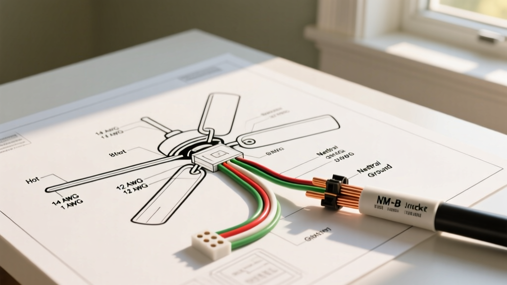
When repairing the L110 harness, never substitute wire gauges. Using undersized wire for high-draw circuits will cause voltage drop, excessive heat, and potential fire hazards.
- Battery to Solenoid / Solenoid to Starter: 10 AWG or 8 AWG (Stranded copper, red).
- Main Power Feed to Ignition Switch: 12 AWG (Red).
- PTO Clutch Feed & Charging Output: 14 AWG (Red/Purple).
- Interlock Switches & Sensor Signals: 16 AWG or 18 AWG (Various colors).
- Connectors: Always use sealed Weather-Pack or Metri-Pack connectors with dielectric grease. Standard unsealed spade terminals will corrode within one season due to exposure to fertilizer dust and moisture.
Final Safety and Operational Checks
After completing any wiring repairs, always verify the safety interlock system before operating the mower. As outlined by the John Deere Safety & Operations Hub, bypassing safety switches to force a tractor to start is a leading cause of severe run-over and laceration injuries. Test the seat switch by starting the tractor, engaging the PTO, and standing up; the engine must stall immediately. Test the reverse implementation option (RIO) switch by attempting to reverse with the PTO engaged; the blades must disengage unless the RIO button is manually depressed.
By methodically following this wiring diagram walkthrough and relying on multimeter data rather than guesswork, you can restore the L110's electrical system to factory reliability, ensuring it continues to perform for years to come.