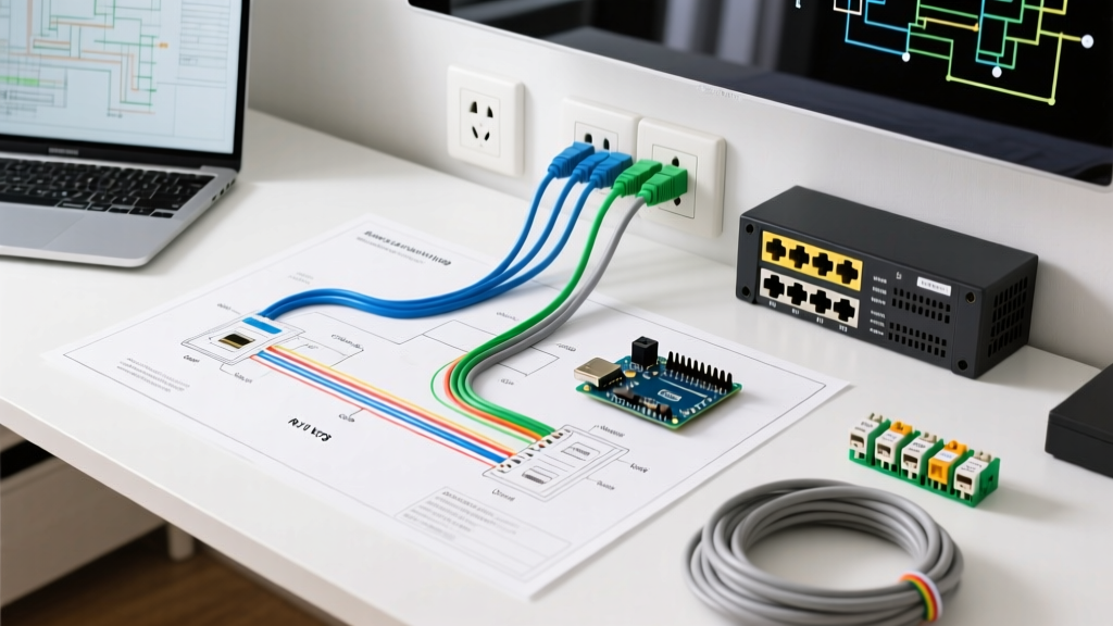

The 2026 Telecom Landscape: POTS vs. PoE VoIP
Planning a telecommunications infrastructure requires a clear understanding of both legacy systems and modern standards. If you are searching for a wiring diagram for phone installations, you are likely navigating the transition between traditional Plain Old Telephone Service (POTS) and modern Power over Ethernet (PoE) Voice over IP (VoIP) systems. With major carriers accelerating copper retirement mandates approved by the FCC, new residential and commercial builds in 2026 almost exclusively rely on Cat6 cabling for voice and data convergence. However, maintaining or retrofitting legacy RJ11 analog lines remains a critical skill for alarm systems, elevator emergency lines, and rural deployments.
This installation planning guide breaks down the exact topologies, pinouts, material costs, and code requirements you need to execute a flawless telecom deployment, whether you are terminating a legacy analog demarc or provisioning a 10Gbps PoE switch for IP handsets.
Decoding the Wiring Diagram for Phone Systems
Legacy RJ11 (POTS) Topology
The traditional wiring diagram for phone lines centers around the Network Interface Device (NID), often called the demarcation point. This is where the carrier’s responsibility ends and the customer’s premises wiring begins. A standard POTS diagram flows from the NID through a 2-pair or 4-pair 24 AWG solid copper cable, daisy-chained or star-wired to RJ11 6P4C wall jacks.
⚠️ Safety Warning: Legacy phone lines carry a nominal -48V DC on-hook voltage, but the ring generator pushes 90V AC at 20Hz during an incoming call. Always verify the line is inactive or use an insulated telecom probe before terminating bare wires to avoid severe shocks, especially if you have a pacemaker.
In a standard 4-wire RJ11 configuration, Line 1 utilizes the inner pair (Red/Green), while Line 2 utilizes the outer pair (Black/Yellow). Modern best practices dictate running a home-run (star topology) from a central structured media enclosure to each jack, rather than daisy-chaining, to simplify troubleshooting and future VoIP conversions.
Modern RJ45 (VoIP/PoE) Topology
The modern wiring diagram for phone systems abandons analog copper in favor of Cat6 (or Cat6A) 8P8C RJ45 connectors. VoIP phones do not require dedicated voice cables; they share the data network. The topology flows from the ISP Modem/Router to a managed PoE switch, then through a structured patch panel, and out to RJ45 keystone jacks. Because IP phones draw power directly from the Ethernet cable via IEEE 802.3af or 802.3at standards, proper cable selection and termination are paramount to prevent voltage drop and thermal issues.
Pinout Standards: RJ11 vs. RJ45 T568B
Miswiring is the leading cause of telecom failures. When adapting a wiring diagram for phone and data, you must adhere to strict pinout standards. Never use legacy voice pinouts for VoIP data lines, as this causes severe crosstalk and packet loss.
| Standard | Connector | Pin 1 | Pin 2 | Pin 3 | Pin 4 | Pin 5 | Pin 6 | Pin 7 | Pin 8 |
|---|---|---|---|---|---|---|---|---|---|
| Legacy POTS (Line 1 & 2) | RJ11 (6P4C) | Unused | Black (L2) | Red (L1) | Green (L1) | Yellow (L2) | Unused | N/A | N/A |
| T568B (VoIP/Data) | RJ45 (8P8C) | Wht/Org | Orange | Wht/Grn | Blue | Wht/Blu | Green | Wht/Brn | Brown |
Note: T568B is the dominant commercial and residential standard in North America for 2026. Always terminate both ends of a VoIP drop to T568B to maintain pair twisting and minimize Near-End Crosstalk (NEXT).
Installation Planning: Step-by-Step Execution
- Pathway Planning & Separation: Map your cable runs. Per NEC guidelines, unshielded twisted pair (UTP) Cat6 must maintain a minimum 2-inch separation from standard 120V AC mains. If running parallel to high-voltage lines, increase separation to 12 inches or use shielded (F/UTP) cable.
- Pulling Tension & Bend Radius: Never exceed 25 pounds of pulling tension on Cat6 cables, as this stretches the copper and alters the twist rate, destroying the cable's impedance. Maintain a bend radius of at least four times the cable diameter (approx. 1 inch).
- Termination at the Patch Panel: Use an 110-style punch-down tool. Ensure the untwisted portion of the wire at the termination point does not exceed 0.5 inches. Exceeding this limit introduces crosstalk that will fail certification testing.
- Keystone Jack Termination: At the wall plate, use T568B color-coded IDC (Insulation Displacement Contact) keystone jacks. Snap them into a standard Decora or 1-gang faceplate.
- PoE Switch Provisioning: Connect the patch panel to a PoE switch. Verify the switch supports IEEE 802.3at (PoE+) if you are deploying IP phones with color LCD screens or sidecar expansion modules, which typically draw 12W to 18W.
2026 Material & Cost Planning Matrix (10-Drop Setup)
Budgeting for a telecom retrofit requires accurate 2026 pricing. Below is a realistic material breakdown for a 10-jack residential or Small Office/Home Office (SOHO) deployment using high-quality, UL-listed components.
| Component | Specification / Model | Estimated Cost (2026) |
|---|---|---|
| Bulk Cable | 1000ft Cat6 23AWG Solid Bare Copper (CMR Riser) | $165.00 |
| Patch Panel | 12-Port Cat6 Unloaded Patch Panel | $35.00 |
| Keystone Jacks | 10x Cat6 RJ45 Toolless IDC Keystones | $45.00 ($4.50/ea) |
| PoE Switch | Netgear GS116PE (16-Port Gigabit, 8-Port PoE+) | $219.00 |
| Testing Tool | Klein Tools VDV226-110 Pass-Thru Crimper Kit | $65.00 |
| Certifier (Optional) | Fluke Networks MicroScanner PoE Verifier | $850.00 |
Pro-Tip: Never purchase Copper Clad Aluminum (CCA) cable. CCA has higher resistance, which causes severe voltage drop over PoE and poses a fire hazard due to heat buildup. Always specify 100% bare copper.
Edge Cases & Critical Failure Modes
- Split Pairs: A common mistake when adapting a wiring diagram for phone is mapping Line 1 and Line 2 to the blue and orange pairs without respecting the twists. In data networks, this creates a "split pair" fault. The signal will transmit, but NEXT (Near-End Crosstalk) will cause massive packet loss, resulting in choppy VoIP audio or dropped calls.
- PoE Thermal Bundling: When bundling Cat6 cables in a conduit or cable tray, the center cables can overheat if all are carrying 30W PoE+. The 2026 TIA-568.2-D standard recommends limiting bundle sizes to 24 cables for 23 AWG Cat6 when utilizing high-wattage PoE to prevent the cable jacket from degrading and insertion loss from spiking.
- Distance Limitations: The absolute maximum channel length for Ethernet (and VoIP) is 100 meters (328 feet). This includes 90 meters of solid horizontal cable and 10 meters of stranded patch cords. If your run exceeds this, you must install an intermediate PoE switch or a managed PoE extender.
Code Compliance & Authoritative References
All telecom installations must adhere to local electrical codes and industry standards. In the United States, the National Electrical Code (NEC) governs these installations under Article 800 (Communications Circuits). Specifically, NEC 800.100 mandates that the primary protector (for legacy POTS) or the metallic sheath of shielded cables must be grounded to the building's grounding electrode system using a minimum 14 AWG copper wire to prevent surges from entering the premises.
For further reading and to ensure your installation planning meets current regulatory and engineering standards, consult the following authoritative resources:
- NFPA 70 (National Electrical Code): Review Article 800 and Article 725 for strict guidelines on cable substitution, plenum ratings (CMP), and grounding requirements for communications circuits.
- IEEE PoE Standards: Familiarize yourself with the IEEE 802.3bt standard to understand the power delivery capabilities and thermal management requirements for modern PoE switches powering IP phones and wireless access points.
- FCC Consumer Guidelines: For understanding carrier demarcation responsibilities and copper retirement policies, refer to the FCC Landline Phone Consumer Guide.
By mastering both the legacy analog topologies and modern PoE data layouts, you ensure that your telecom infrastructure is robust, code-compliant, and future-proofed for the next decade of digital communication.