
Mastering the 60A Wiring Diagram for a Sub Panel: Heavy Appliance Edition
As home electrification accelerates in 2026, adding high-draw appliances like Level 2 EV chargers, tankless water heaters, or workshop welders often exceeds the spatial and thermal limits of your main service panel. The most reliable, code-compliant solution is installing a dedicated 60-amp subpanel. However, executing a wiring diagram for a sub panel requires strict adherence to the National Electrical Code (NEC), particularly regarding neutral-to-ground isolation and continuous load calculations.
This comprehensive tutorial breaks down the exact schematic, material requirements, and failure modes associated with wiring a 60A subpanel specifically for heavy appliance circuits. Whether you are a seasoned DIYer or an apprentice electrician, this guide provides the actionable depth needed to pass your local Authority Having Jurisdiction (AHJ) inspection on the first try.
Core Components & 2026 Material Pricing
Before tracing the wiring diagram for a sub panel, you must procure the correct hardware. Undersizing lugs or using mismatched bus bars are common reasons for inspection failures. Below is a breakdown of recommended 2026 market components and their average retail costs.
| Component | Recommended Model | Specifications | Avg. Cost |
|---|---|---|---|
| Main Panel Breaker | Square D HOM260 | 60A, 2-Pole, 120/240V, 10kAIC | $32.00 |
| Sub Panel Enclosure | Siemens P2S60L1100CU | 60A Main Lugs, 2-Space, 4-Circuit, NEMA 3R | $68.00 |
| Feeder Wire (Copper) | Southwire THHN/THWN-2 | 6 AWG Stranded Copper (Black, Red, White, Green) | $2.80 / ft |
| Feeder Wire (Aluminum) | Cerrowire XHHW-2 | 4 AWG Aluminum (2-2-2-4 MHF equivalent) | $1.25 / ft |
| Torque Screwdriver | Klein Tools 625-6 | Calibrated 10-60 in-lb range (NEC 110.14 compliant) | $145.00 |
Decoding the Wiring Diagram for a Sub Panel
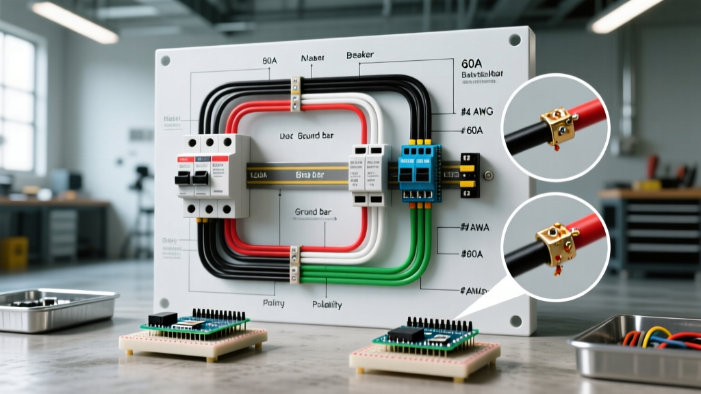
A standard 60A appliance subpanel wiring diagram consists of three distinct zones: the main panel termination, the feeder run, and the subpanel termination. The most critical concept to internalize is that the neutral and ground must remain strictly separated at the subpanel.
Zone 1: Main Panel Feeder Termination
- Shut Off Main Power: Verify zero voltage at the bus bars using a CAT IV multimeter.
- Install the 60A Breaker: Snap the Square D HOM260 into an available dual slot on the main bus bar. Ensure it seats firmly with an audible click.
- Land the Hot Conductors: Strip 5/8 inch of insulation from the Black (L1) and Red (L2) 6 AWG THHN wires. Insert them into the breaker lugs. Critical: Use your calibrated torque screwdriver set to 35 in-lbs (verify against the breaker's printed spec sheet) to tighten the set screws.
- Land Neutral and Ground: Terminate the White (Neutral) wire to the main panel's isolated neutral bar, and the Bare/Green (Ground) wire to the main grounding bus bar. Never double-lug wires; use separate terminal holes.
Zone 2: The Feeder Run & Wire Gauge Rules
The wire gauge you select dictates the physical routing of your diagram. A common and dangerous DIY mistake is using 6 AWG NM-B (Romex) for a 60A breaker. Under NEC Table 310.15(B)(16), NM-B cable is restricted to the 60°C column. In the 60°C column, 6 AWG copper is only rated for 55 Amps. Therefore, you must use 4 AWG NM-B if running Romex, or 6 AWG THHN in conduit (which utilizes the 75°C/90°C column, rated for 65A/75A, safely protected by a 60A breaker).
Pull all four conductors (Black, Red, White, Green) through a minimum 1-inch PVC Schedule 80 or EMT metallic conduit. Maintain a 1/4-inch bend radius to prevent insulation scoring.
Zone 3: Sub Panel Termination & Isolation
This is where the wiring diagram for a sub panel differs fundamentally from a main panel.
- Remove the Bonding Strap: Locate the green bonding screw or copper strap connecting the neutral bus bar to the metal chassis of the subpanel. Remove it entirely.
- Land the Hots: Connect Black and Red to the subpanel's main lugs. Torque to 45 in-lbs.
- Land the Neutral: Connect the White wire to the isolated neutral bus bar. Torque to 35 in-lbs.
- Land the Ground: Connect the Green/Bare wire to the dedicated grounding bus bar (which remains bonded to the metal chassis).
NEC Safety Warning: According to the National Fire Protection Association (NFPA) guidelines on NEC 250.24(A)(5), bonding the neutral and ground at a sub-panel creates a parallel path for return current. This energizes the metal chassis of your appliances and enclosures, presenting a severe shock and fire hazard.
Appliance Load Calculations & Smart Shedding
When designing your subpanel for heavy appliances, you must account for continuous versus non-continuous loads. The U.S. Department of Energy notes that Level 2 EV chargers are considered continuous loads (operating for 3 hours or more). NEC Article 210.20 requires continuous loads to be derated by 125%.
Load Scenario: EV Charger + Mini-Split HVAC
Suppose you are wiring a 48A hardwired EV charger and a 20A mini-split heat pump to this 60A subpanel.
- EV Charger: 48A continuous x 1.25 = 60A required circuit capacity.
- Mini-Split: 16A actual draw (non-continuous).
- Total Demand: 76A. This exceeds your 60A feeder limit.
The 2026 Solution: Instead of upgrading to a $2,500 100A feeder, install an automated load-shedding relay (such as the Emporia VUE or a Wallbox Power Sharing module). These devices monitor the EV charger's draw and temporarily throttle the charging amperage down to 30A when the mini-slip compressor kicks on, ensuring the 60A subpanel feeder never trips.
Critical Failure Modes & Edge Cases
Even with a perfect wiring diagram for a sub panel on paper, physical installation errors cause 90% of failed inspections and electrical fires. Avoid these specific edge cases:
1. The Detached Building Grounding Electrode
If your subpanel is located in a detached garage or workshop, NEC 250.32 mandates a Grounding Electrode System (GES) at the detached structure. You must drive two 5/8-inch copper ground rods, spaced at least 6 feet apart, and connect them to the subpanel's grounding bus bar using a continuous 8 AWG bare copper conductor. Do not do this if the subpanel is attached to the main house.
2. Aluminum Oxidation at Lugs
If you opted for 4 AWG Aluminum XHHW-2 feeder wire to save money, you must apply an anti-oxidant compound (like Noalox) to the stripped aluminum wire before inserting it into the panel lugs. Aluminum oxidizes rapidly when exposed to air, creating a high-resistance layer that generates intense heat and melts lug housings over time.
3. Conduit Fill Capacity Violations
Pushing four 4 AWG aluminum wires into a 3/4-inch PVC conduit violates NEC Chapter 9, Table 1 (40% fill capacity rule). The friction will strip the wire insulation during the pull, causing a dead short. Always use a minimum 1-inch conduit for a 4-wire 60A feeder, and use wire pulling lubricant (Polywater) to reduce tension.
Expert FAQ: Sub Panel Wiring Nuances
Can I use a main breaker panel as a subpanel?
Yes. You can buy a 100A main breaker panel and feed it with a 60A breaker from the main service. The 100A main breaker in the subpanel simply acts as a local disconnect switch. Ensure you still remove the neutral-to-ground bonding strap behind the main breaker assembly.
Do I need a 4-wire feeder for an existing 3-wire setup?
For any new installation or modification in 2026, a 4-wire feeder (two hots, one neutral, one ground) is strictly required by the NEC. The old 3-wire rule (which allowed the neutral and ground to bond at the subpanel and use the neutral as a ground path) was eliminated in the 2008 NEC cycle due to fatal shock hazards. If you are upgrading an appliance circuit, you must pull a new 4-wire feeder.
What size grounding conductor do I need for a 60A feeder?
Per NEC Table 250.122, a 60A overcurrent protective device requires a minimum 10 AWG copper or 8 AWG aluminum equipment grounding conductor. However, most electricians pull an 8 AWG copper ground as a standard practice to provide a robust fault-current path and reduce voltage drop during a short circuit event.