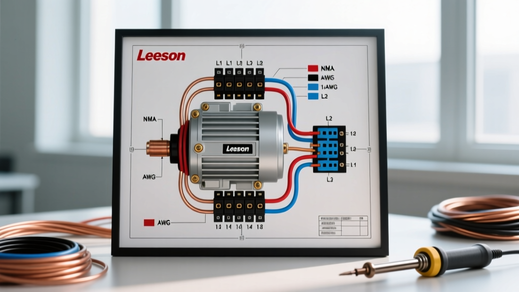

Introduction to Leeson NEMA Motors and 2026 Wiring Standards
Leeson, now a flagship brand under the Regal Rexnord umbrella, remains one of the most trusted names in industrial and agricultural electric motors. As of 2026, the Department of Energy (DOE) has strictly enforced IE3 and IE4 premium efficiency mandates for most integral horsepower motors. While these high-efficiency designs reduce overall power consumption, they do not eliminate the need for precise electrical sizing. In fact, the integration of advanced thermal protection and variable frequency drive (VFD) compatibility in modern Leeson motors makes understanding the exact Leeson electric motor wiring diagram more critical than ever.
Unlike consumer electronics, industrial motors do not rely on a universal "color code" for their internal windings. Instead, they adhere to the National Electrical Manufacturers Association (NEMA) MG 1 standard, which utilizes numbered leads (T-leads) and specific termination configurations. This guide provides an authoritative reference for decoding Leeson motor leads, selecting the correct wire gauge per NEC Article 430, and avoiding the most common termination failures in the field.
Decoding Leeson Motor Lead Markings and "Color Codes"
A common point of confusion for electricians transitioning from IEC (European) standards to NEMA (North American) standards is the expectation of colored insulation. IEC motors typically use Brown, Black, and Gray for three-phase power. However, NEMA MG 1-2.20 standards dictate that Leeson motor leads are typically black THHN/THWN wire with identifying markers, numbered tape, or printed tags.
Single-Phase Leeson Motors (Capacitor-Start/Run)
Single-phase Leeson motors, such as the popular Farm Duty and General Purpose lines, are usually dual-voltage (115/230V). The wiring diagram on the motor's nameplate will reference either a 4-lead or an 8-lead configuration.
- 4-Lead Configuration: Uses leads marked T1, T2, T3, and T4 (or simply 1, 2, 3, 4). T1 and T4 are the main run winding, while T2 and T3 are the start/auxiliary winding.
- 8-Lead Configuration: Used for larger single-phase motors (typically 3HP and above) to allow for series/parallel winding connections. Leads are numbered 1 through 8. For 230V operation, the run windings are wired in series; for 115V, they are wired in parallel.
- Color Exceptions: In some older or specific OEM Leeson single-phase models, you may encounter colored pigtails: Black and White for the main run winding, and Red and Yellow for the start winding. Always defer to the physical nameplate diagram over generic color assumptions.
Three-Phase Leeson Motors (9-Lead Dual Voltage)
Three-phase Leeson motors (e.g., the 116715 3HP inverter-duty model) utilize a 9-lead system for dual voltage (230/460V). The leads are marked T1 through T9. The internal winding configuration is either Wye (Star) or Delta, which drastically changes how you jumper the leads in the peckerhead (connection box).
| Motor Type | Voltage | Wiring Configuration (Jumpered Leads) | Line Power Connection |
|---|---|---|---|
| Wye (Star) | High (460V) | T4-T7, T5-T8, T6-T9 (Tied together) | L1 to T1, L2 to T2, L3 to T3 |
| Wye (Star) | Low (230V) | T1-T7, T2-T8, T3-T9, T4-T5-T6 | L1 to T1/T7, L2 to T2/T8, L3 to T3/T9 |
| Delta | High (460V) | T4-T7, T5-T8, T6-T9 | L1 to T1/T7, L2 to T2/T8, L3 to T3/T9 |
| Delta | Low (230V) | T1-T6-T7, T2-T4-T8, T3-T5-T9 | L1 to T1/T6/T7, L2 to T2/T4/T8, L3 to T3/T5/T9 |
Wire Gauge Selection: Sizing for Leeson FLA and NEC 430
Selecting the correct wire gauge is not based on the motor's horsepower alone; it is strictly dictated by the Full Load Amps (FLA) or Full Load Current (FLC) listed on the Leeson nameplate, combined with the rules set forth in NEC Article 430.
The NEC 125% Rule: According to NEC 430.22, branch circuit conductors supplying a single motor must have an ampacity of not less than 125% of the motor's full-load current rating. You must calculate the wire size based on this 125% multiplier, not the raw FLA.
Wire Gauge Sizing Chart for Common Leeson HP Ratings
The following table provides baseline wire gauge selections for common Leeson NEMA frame motors using 75°C rated THHN copper conductors in an ambient temperature of 30°C (86°F). Always verify the exact FLA on your specific motor's nameplate, as premium efficiency (IE4) models introduced in 2026 may have slightly lower FLA draws than legacy models.
| Motor HP | Phase | Voltage | Approx. Nameplate FLA | 125% Calculation | Min. Wire Gauge (AWG) | Max Inverse-Time Breaker |
|---|---|---|---|---|---|---|
| 1 HP | 1-Phase | 115V | 16.0 A | 20.0 A | 10 AWG | 30 A |
| 2 HP | 1-Phase | 230V | 12.0 A | 15.0 A | 12 AWG | 25 A |
| 3 HP | 3-Phase | 230V | 9.6 A | 12.0 A | 12 AWG | 25 A |
| 5 HP | 3-Phase | 230V | 15.2 A | 19.0 A | 10 AWG | 40 A |
| 7.5 HP | 3-Phase | 460V | 11.0 A | 13.75 A | 12 AWG | 25 A |
| 10 HP | 3-Phase | 460V | 14.0 A | 17.5 A | 10 AWG | 35 A |
Voltage Drop: The Hidden Killer of Agricultural Motors
Leeson's "Farm Duty" and "Harsh Duty" motors are frequently installed in agricultural settings where the distance from the main service panel to the motor (e.g., a grain auger or irrigation pump) can exceed 150 feet. The NEC recommends a maximum voltage drop of 3% for branch circuits and 5% overall. A 230V motor operating at 218V due to line loss will draw significantly higher amperage to produce the same mechanical torque, leading to rapid degradation of the winding insulation and premature thermal overload trips.
Actionable Rule: For every 100 feet of run beyond 50 feet, upsize your copper wire gauge by one step. For example, if a 5HP 230V Leeson motor requires 10 AWG wire per NEC 430, but the run is 250 feet, you must upgrade to 6 AWG copper to maintain the voltage within the 3% threshold.
Step-by-Step: Terminating a 2HP Leeson C145T17FB2C (Single-Phase)
The Leeson C145T17FB2C is a ubiquitous 2HP, 1725 RPM, 115/230V single-phase motor. Here is the exact procedure for wiring this unit for 230V operation, which is highly recommended to reduce current draw and heat generation.
- Verify Power & Lockout: Ensure the branch circuit breaker is locked out and tagged out (LOTO). Verify zero voltage with a CAT III multimeter.
- Access the Peckerhead: Remove the four screws securing the connection box cover on the side of the motor. Locate the wiring diagram sticker on the inside of the cover.
- Configure for 230V: Identify the 8 leads. Connect lead 2 to lead 3 and insulate with a wire nut. Connect lead 4, 5, and 8 together. Connect lead 1 to Line 1 (Hot), and connect lead 6 and 7 to Line 2 (Hot). *Note: Always double-check this against the specific diagram on your motor, as internal revisions occur.*
- Strip and Terminate: Strip exactly 5/8 inch of insulation from your THHN supply wires. If using stranded wire, crimp on insulated ring terminals. Do not use fork terminals in high-vibration environments, as they can slip off the terminal block screws.
- Torque to Spec: Tighten the terminal block screws to 15-20 in-lbs. Under-torquing causes arcing and carbon buildup; over-torquing can strip the brass threads on the motor's internal terminal board.
- Grounding: Connect the equipment grounding conductor (EGC) to the dedicated green grounding screw inside the peckerhead. The EGC must be sized per NEC 250.122 (typically 10 AWG for a 30A breaker).
Common Wiring Failures and Troubleshooting Edge Cases
Even with a perfect Leeson motor wiring diagram reference, field conditions introduce variables that cause failures. Be prepared to troubleshoot the following edge cases:
- Thermal Overload (OL) Nuisance Tripping: If the red reset button on the motor's thermal protector pops within 5 minutes of startup, check for voltage drop. A 5% drop in voltage results in a 10% increase in amperage draw. Also, verify the ambient temperature; if the motor is in a 110°F+ environment, the standard internal OL may be underrated.
- Reversed Rotation on 3-Phase Motors: If a Leeson 3-phase motor spins backward (e.g., on a centrifugal pump), do not rewire the entire panel. Simply swap any two of the three T-leads (e.g., swap T1 and T2) at the motor peckerhead to reverse the magnetic field sequence.
- Capacitor Failure on Single-Phase: If the motor hums but fails to start, and the wiring is correct, the start capacitor has likely failed. Use a multimeter with a capacitance setting to test the microfarad (µF) rating. Replace with an exact µF and voltage match (e.g., 216-259 µF, 250VAC).
- VFD Compatibility Issues: If you are wiring a Leeson Inverter Duty motor to a VFD, you must use symmetrical shielded VFD cable (e.g., 3-conductor with 3 symmetric grounds). Standard THHN in conduit can cause reflected wave voltage spikes that puncture the motor's winding insulation over time.
Authoritative References
For ongoing compliance and technical verification, always consult the primary regulatory and manufacturing bodies:
- National Fire Protection Association (NFPA): National Electrical Code (NEC) Article 430 - Motors, Motor Circuits, and Controllers.
- Regal Rexnord: Leeson Technical Documentation and Warranty Guidelines.
- NEMA: NEMA MG 1 Motors and Generators Standard - Section 2 (Marking and Terminal Connections).